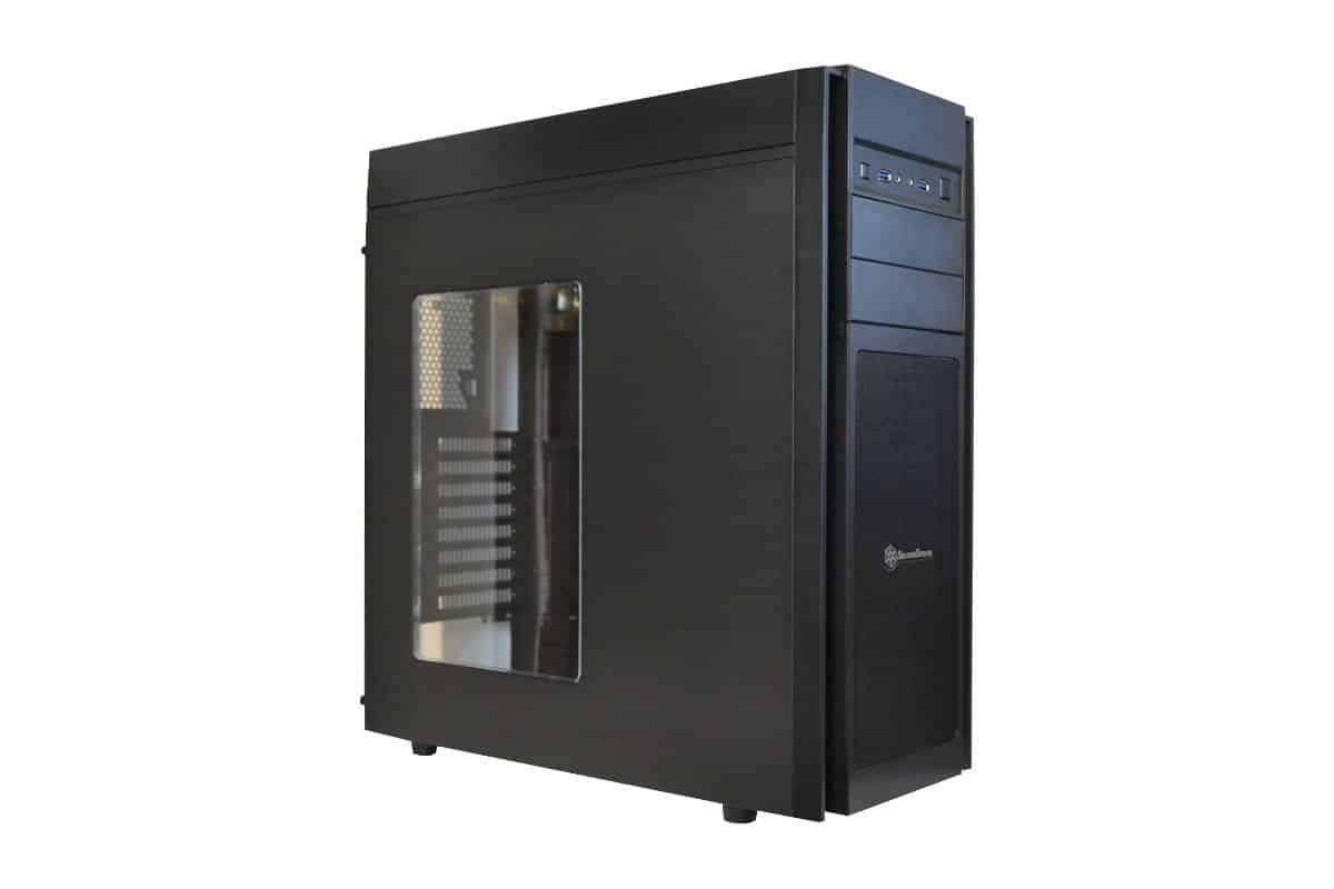
Inside the SilverStone Kublai KL05-W Case
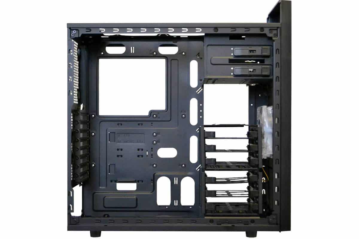
This metal frame of the case is very thin but not to the point of being flimsy. All the standoffs have to be manually installed and the case has no M.A.P. (Motherboard Alignment Pin) so you have to mount the motherboard old school style which is to carefully line the back I/O panel first then gently lay the motherboard down on the standoffs and align the center or the bottom right hand standoff first. I know, everyone has a different way to do this and all of us think we know best but I offer my own way of doing it. Then I press the top right screw into the standoff and then do the rest.
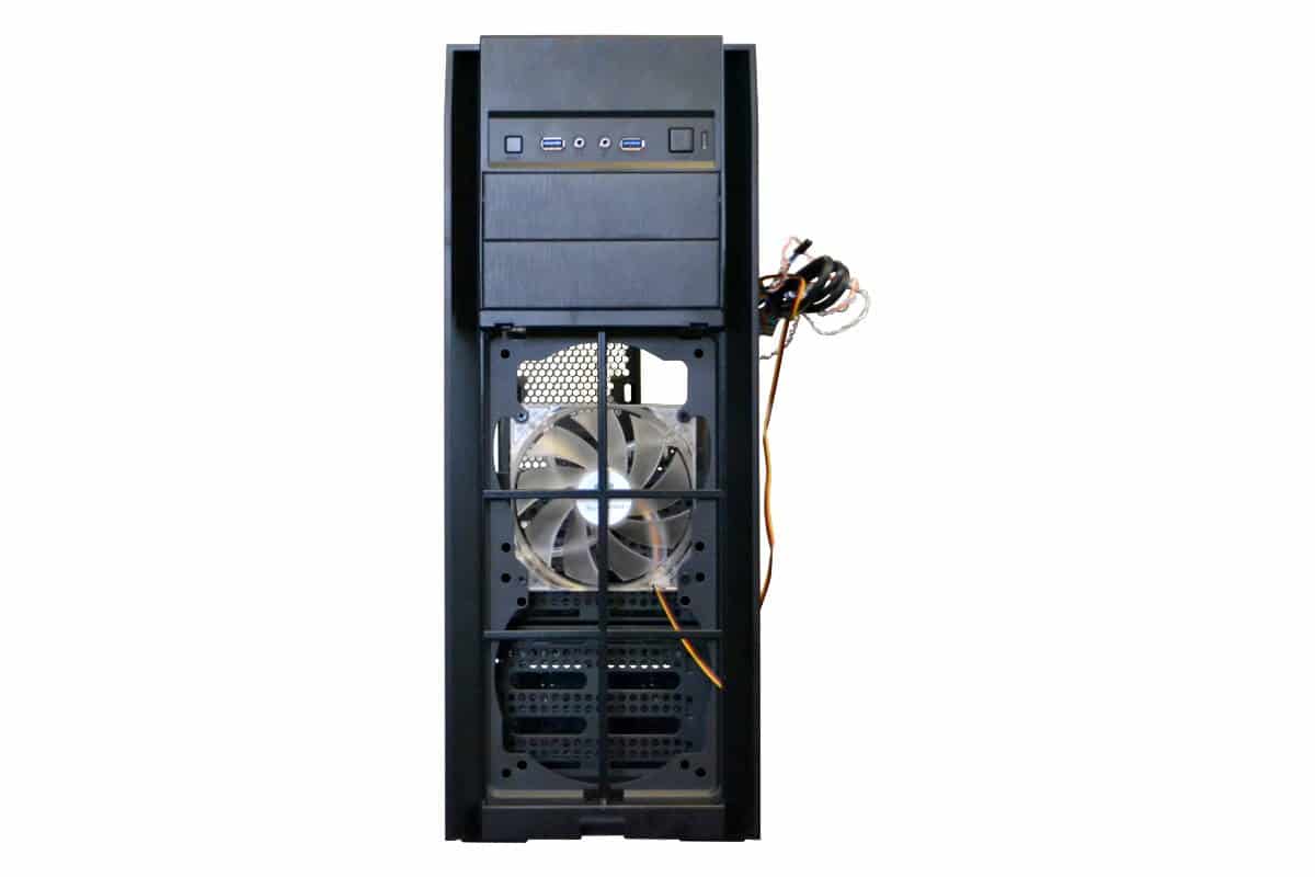
The front fan filter cover is extremely easy to remove from the bottom. Just feel for the middle notch in the cover under the middle front of the case and pull out the bottom first then drip down some to allow the two plastic tabs to fall from their position. The 120mm fan is a very bright blue colored silent running fan but pretty small for the opening. In my build I used some regular black Lian Li 140x140mm fans to replace this one and moved this smaller one to the back of the case for an exhaust fan.
The way that the Hard drive modules are standard located at the bottom, it does cut a lot of the circulation off from the air entering the case from the front, so I simply removed them from the original placement and used the top module fitting for a single 3 drive module over the fans.
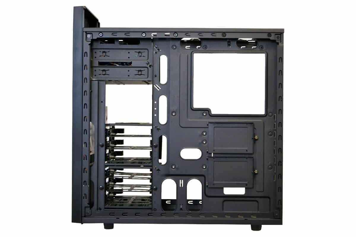
The back motherboard CPU access point is built correctly and does conform to ATX motherboard CPU Placement. There are also two CPU power (P4/P8) connector holes at the top for different motherboard configurations. The clearance in the back of the motherboard is sufficient to wire with 3/4 of an inch of clearance between the panel and the motherboard tray. The tie offs are set up logically on a C.A.D. machine but really have no real serviceable reason for being there except for me to say that there are 5 of them. The wire management holes were useful and almost lined up with my SATA Ports but I really used the large open area in the drive area for most of my wire management work.
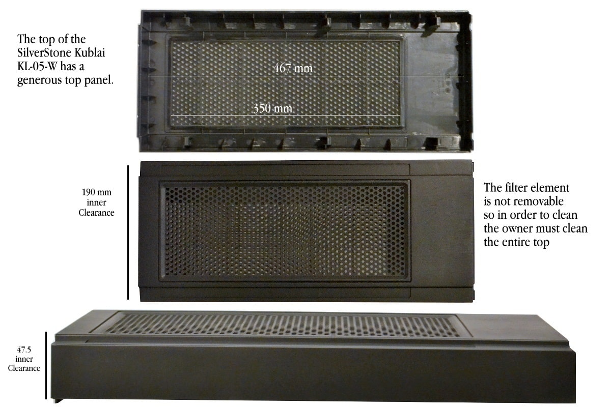
Here is a look of the top, bottom and side view of the top hat type cover and the clearance measurements that you may need in the future as a reference for this case. Unfortunately, The top filter element is glued securely to the top of the panel so you will have to wash the entire top for cleaning which is not too bad since it is so easy to remove the top cover with the two thumbscrews at the back and pull back lip under the front cover.
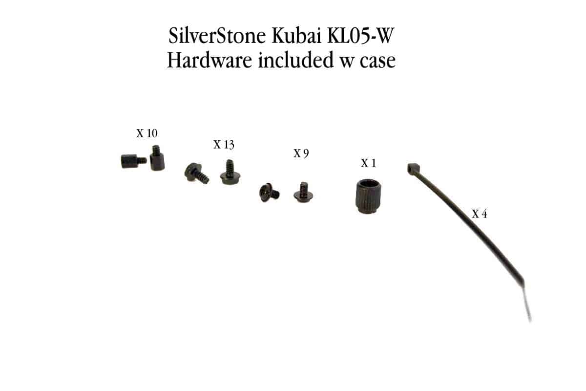
The hardware is sufficient and the motherboard standoff tool that looks like it would fit on the valve stem to inflate your car tire works really great and has a Phillips head fitting on the top to let you torque down the standoffs and 4 wire ties total. I don’t know about you, but I use four times that many wire ties on an average build but that is me. I buy them in bulk at the Auto Supply place down the road for a couple of bucks.
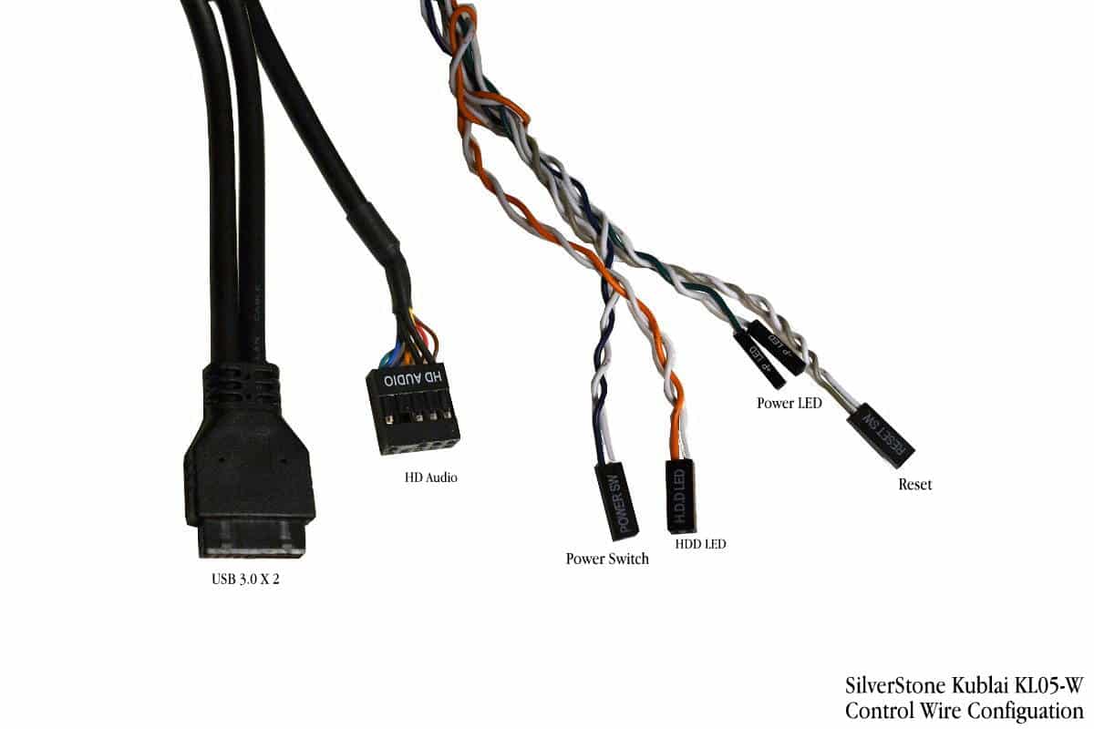
The front panel control wires are simple enough and long enough except the HD Audio wire. Mine seemed to be about 3 inches too short so I had to route my wire over the board and route it under my video card so keep that in mind if you are using this case. This little thing could turn into a real head-scratcher if you don’t think about it while your building.
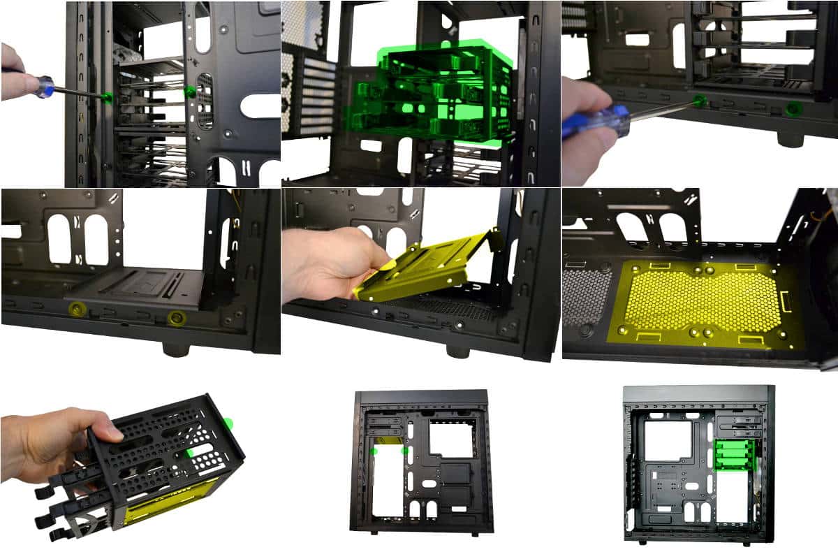
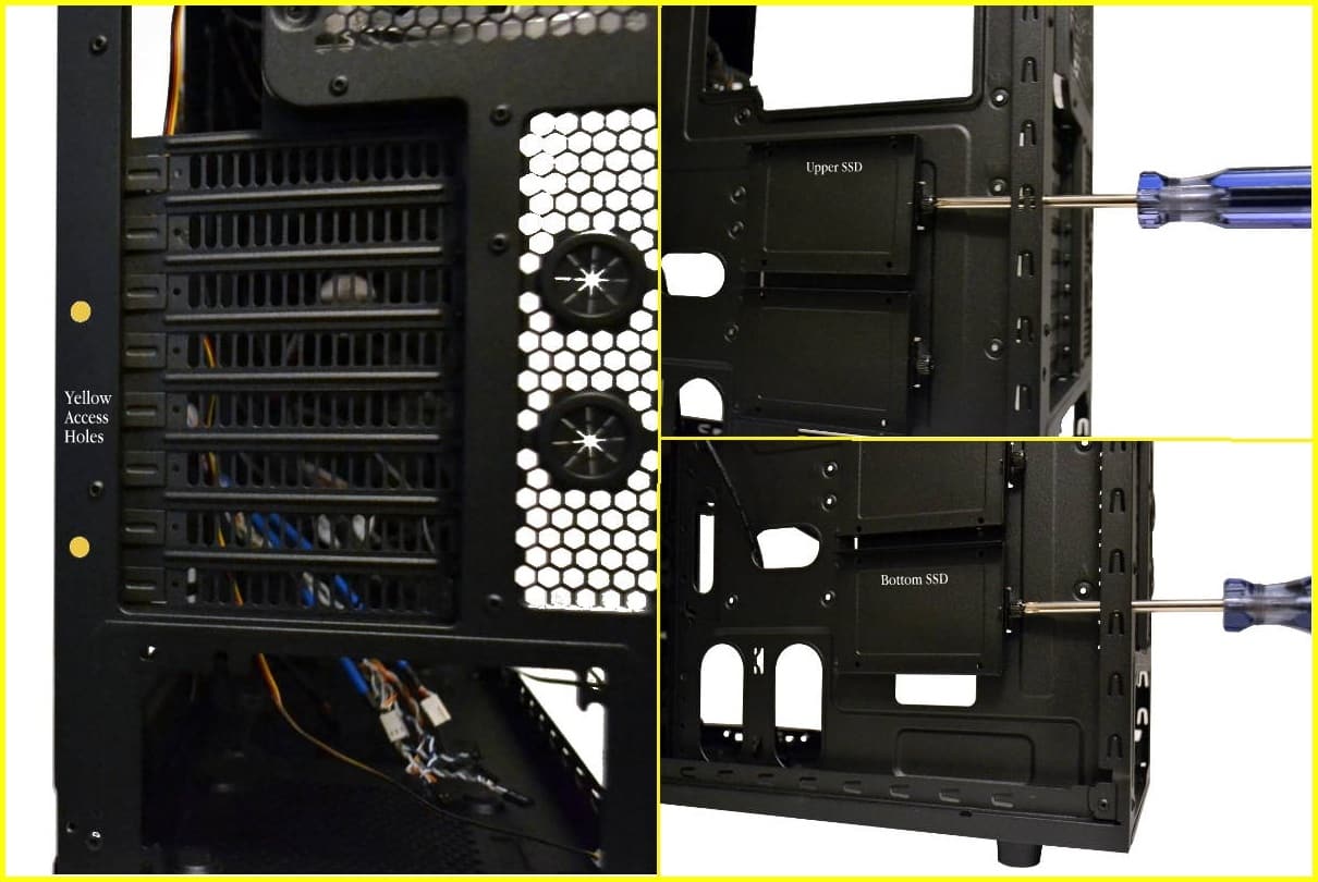
One thing that I really liked about this case was the two holes made purposely to place your screwdriver through to get to the back mounted SSD screws. This is the first time I have ever noticed this but I loved it. Here it is marked in yellow on the left side picture and as you can see from the other two pictures the Phillips head screw driver fits perfectly through the hole to tighten down the SSD mount screw.
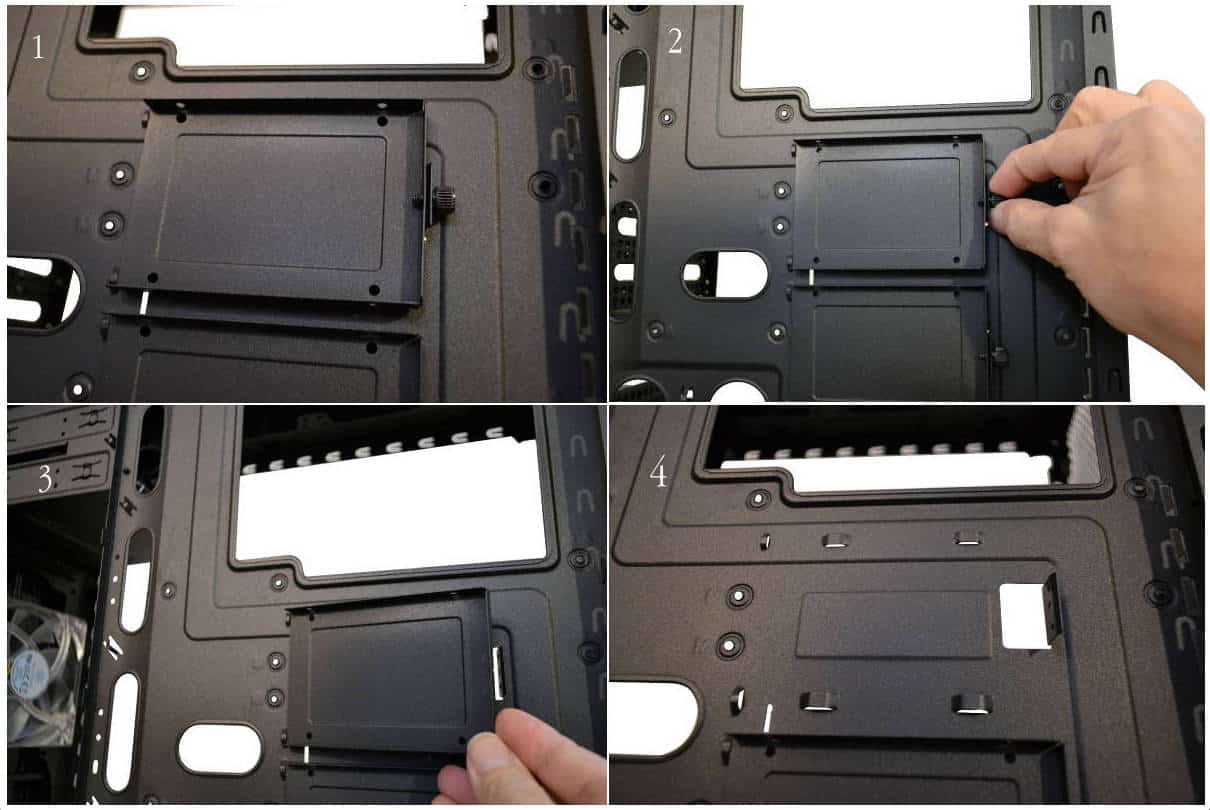
Each portioned of this four part description is numbered from 1-4. One shows the SSD drive tray in the locked position. 2 shows the removal of the thumbscrew that holds the tray in place. 3 shows pulling the drive away from the motherboard tray. 4 is interesting as it shows the four standoffs that keep the tray lifted from the motherboard back tray for easier plugging in of wires. This is also a plus to this economy case.
The figures shown below describes how all of the drive bay modules at the bottom drive bay mount and how they can be removed for installing a bottom water cooling radiator if desired. The bottom plate is held on by four screws and easily lifted away for storage. As you can see I moved my one module all the way to the top of the 5.25 bay rail to use for my build. It was a very easy procedure to move the modules around as you might need for your particular build or mod and there were mounting screws for top mounting as well.