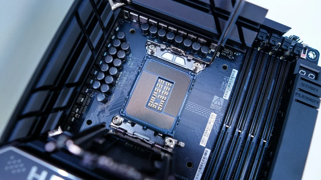
Why VRM quality dictates stable overclocks
A great overclock doesn’t start with a magic vCore or the perfect LLC preset. It starts with the power path. Your motherboard’s VRM turns the PSU’s 12V into a tightly regulated, low‑voltage rail that your CPU can gulp without tripping over ripple, droop, or heat. When power stages run too hot, inductors flirt with saturation, or cap banks can’t soak transients, the result is the same: lost frequency headroom, weird stutters under bursty loads, or outright throttling.
This guide translates datasheets and marketing blurbs into practical rules you can apply in five minutes. You’ll learn how to judge a board’s VRM parts, spot smart heatsink designs, pick caps and inductors that don’t fold under AVX spikes, and build a quick worksheet you can re‑use on every build.
Power stages, phases, and current ratings—what actually matters
More phases can help, but “22+1+2+2” on a box isn’t a guarantee. What matters is the quality of the power stages, the PWM controller’s behavior, and the cooling wrapped around them.
- DrMOS vs. discrete MOSFETs: Integrated driver‑MOSFET packages (DrMOS/Smart Power Stages) reduce parasitics and can improve switching efficiency and transient response. Discrete arrangements can still be excellent, but layout and gate‑drive tuning become more critical.
- Rated amps vs. sustainable amps: A “90A” or “110A” stage rating doesn’t mean continuous 90A at case temps you’ll actually see. Ambient temperature, VRM heatsink mass/finning, thermal pad contact, and case airflow set your real ceiling.
- “True” phases vs. doublers/teamed: Doublers can reduce ripple and spread thermals, but they don’t behave identically to more independent phases during fast load steps. If you’re pushing all‑core boosts with gnarly transients, phase quality and control loop tuning matter as much as count.
Real‑world anchor points help here:
- The ASUS ROG Maximus Z890 Hero pairs a 22‑phase vCore with robust cooling; even in high ambient, TechPowerUp measured peak VRM temps of 53°C after extended stress testing, and noted heatpipe‑linked heatsinks plus a thermally‑active backplate.
- That board uses two DIGI+ EPU PWM controllers (ASP2412 and ASP2414), and its VRM mix includes Infineon PMC4130 100A stages alongside PMC41420 and MPS87681 parts—evidence that controller choice and stage selection go hand‑in‑hand with thermal design.
Bottom line: Don’t stop at “amp per phase” math. Ask: What controller is driving it? How good is the contact to a real heatsink (not just a pretty shroud)? Where is the airflow? And what temperatures do reviews record under sustained load?
Capacitor grades you actually care about
Capacitors around the socket aren’t all doing the same job. Treat them as a team:
- MLCC arrays (ceramic) close to the die handle the nastiest high‑frequency content thanks to low ESL/ESR. Watch DC‑bias derating—effective capacitance drops under bias—and be mindful of mechanical stress near rigid heatsinks.
- Solid polymer electrolytics (often near the chokes) serve as bulk storage to flatten ripple across lower frequencies. They offer low ESR and high ripple current handling across temperature, which is why they’re standard in modern vCore banks.
- Polymer tantalum or specialty polymers sometimes appear where steady loads and long life are prized; if you swap parts, derate generously for surge and temperature.
Practical heuristics when evaluating or replacing caps:
- Don’t chase “lowest ESR at all costs.” You need enough damping for loop stability. In mixed banks, the controller, output inductor values, and total capacitance set that dance.
- Favor 105–125°C endurance ratings for parts within the VRM’s heat shadow.
- For ripple current, aim for at least 1.5–2.0× your expected RMS current contribution per device; modern polymer series typically publish generous ripple specs.
- If you must replace a failed cap, match ESR class and ripple capability first; stepping up one voltage bin can improve life through derating, as long as size/footprint fit.
Signs you’re pushing too far: load‑step crackles in audio, intermittent WHEA errors, or sudden clock drops when you hit bursty, cache‑heavy workloads. That’s often ripple/loop‑stability trouble—not just “vCore too low.”
Inductors/chokes decoded: saturation current, DCR, and core materials
Inductors (chokes) are the unsung heroes in vCore stability. Three specs matter most:
- Isat (saturation current): Size for peaks, not averages. When you slam into soft saturation, inductance drops, ripple balloons, heat rises, and the controller must work harder. As a rule of thumb for OC headroom, spec Isat at ≥1.5× your estimated peak per‑phase current.
- Irms (heating current): That’s your temperature rise driver. Ensure Irms coverage with margin given your case airflow and VRM heatsink situation.
- DCR (DC resistance): Lower DCR cuts conduction loss, but often means bigger packages or different core materials. Tiny, low‑profile chokes with very low DCR exist, but they need matching VRM cooling to avoid becoming hot spots.
Core and construction notes:
- Ferrite cores offer low losses at high frequency; powdered iron or “alloy” marketing blurbs can be fine, but look for vendors that publish real curves for inductance vs. current and temperature.
- Coil whine stems from mechanical vibration of the coil/core at certain frequencies and load steps. It’s not “dangerous,” but it’s a sign of the switching/ripple regime you’re operating in. Adjusting LLC, switching frequency, or case damping can help.
A quick sanity check without a microscope: part size (height/footprint), any legible series IDs in review photos, and the board’s measured VRM temperatures under load. If the chokes discolor or the varnish softens during your stress tests, you’re running too hot.
Reading a motherboard’s component bill without the marketing haze
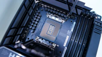
You’ll often see “22+1+2+2” or “10+2+1” power delivery in spec sheets. Translate that into rails: vCore (the big one), SOC, iGPU, and sometimes auxiliary rails. Then connect the dots to controller and power stage choices.
- What to look for in reviews/teardowns: specific PWM controller model(s), stage brands and ratings, heatsink mass/heatpipes, and whether the backplate is actually part of the thermal design.
- Red flags: skinny, un‑finned “heatsinks” that are mostly cover plates; no heatpipe linking both banks; IO shrouds that block airflow; pads that don’t fully cover the hottest stage rows.
If the marketing copy is vague, the teardown photos won’t be. That’s where you’ll spot real pad coverage, heatsink geometry, and the controller/stage lineup you can cross‑reference.
Thermals in practice: small boards, fans, and when airflow saves the day
Mini‑ITX and dense ATX designs change the rules. When space is tight, vendors sometimes add a tiny VRM fan—and it can make or break stability on top‑tier CPUs in small cases.
Heatsink design matters just as much as the fan: heatpipes to share load, finning oriented toward your nearest case fan, and backplates that actually make thermal contact to the rear MOSFET banks.
Fast airflow wins more often than thick metal. If your VRM sits starved under a closed shroud, try:
- Reversing or re‑aiming a top/rear case fan to wash across the heatsink.
- Adding a slim 80/92 mm helper fan at low RPM aimed at the VRM bank (zip‑tied brackets work surprisingly well).
- Lowering RAM heatsink obstruction with shorter DIMMs or moving a top radiator forward to free the VRM’s exhaust path.
The worksheet: evaluate your board’s VRM for overclocking
Run through this once per build and stash the notes with your BIOS profiles.
- Identify the control loop
- PWM controller(s) model and vendor.
- Load‑line calibration (LLC) options and switching‑frequency range.
- Map the phases and stages
- Count vCore phases vs. doublers/teamed.
- Record stage models and “A” ratings; note any mixed stage types across banks.
- Audit the cooling
- Heatsink mass, finning, and any heatpipes.
- Thermal pad coverage (front and back); does the backplate pull heat?
- Case airflow path across VRM.
- Check inductor and cap banks
- Inductors: Isat, Irms, DCR if available; look for reputable series.
- Capacitors: polymer/MLCC mix, ripple current budget, temperature rating.
- Validate under load
- Log VRM temps during your harshest workload for 10–15 minutes.
- Watch vCore droop/recovery at load steps; avoid aggressive LLC that masks issues by overshoot.
- Targets: <70–80°C sustained on VRM sensors in your actual case; lower is better for headroom.
Quick instrumentation tips that prevent RMAs
- Favor hardware measurements when possible. Software power/temperature telemetry can be misleading depending on board vendor implementation.
- As a cautionary example, some platforms route more load through the 24‑pin ATX rails than you’d expect, which can skew readings if you only watch EPS lines; GamersNexus documented unusual rail distribution and explained why isolating rails matters for accurate conclusions.
- An inexpensive IR thermometer (or, better, a thermal camera) pays for itself; take baseline hotspot temps, reseat heatsinks/pads if needed, then retest.
Sourcing and documentation (builder resources)
You don’t need to be an EE to source solid parts—just be picky about datasheets and provenance.
- Cross‑reference PWM controllers and power stages from teardown photos or reviews; most major vendors publish full datasheets or at least current/thermal curves.
- Stick with reputable cap and choke series and watch for counterfeit‑prone parts in second‑hand marketplaces.
- If you need specific ICs, passives, or connectors for repairs or small‑batch mods, consider RFQ‑based sourcing through ICRFQ for hard‑to‑find or obsolete components.
Caveats and counterpoints
- The silicon lottery still rules; two “identical” CPUs can land hundreds of MHz apart under the same VRM.
- Past a point, GPU, memory subsystem, or the game engine takes over as your limiting factor—especially at higher resolutions.
- Modding heatsinks or adding fans can void warranties. Know the risks, and document your changes for future service.
Wrap‑up
Strong overclocks are built on parts that stay cool and behave cleanly when the load snaps from idle to full tilt. Read past the spec sheet: controller, stage quality, heatsink design, and airflow decide whether your voltage is genuinely stable or just lucky. Use the worksheet once, keep your notes, and you’ll make smarter calls on the next build without guessing.