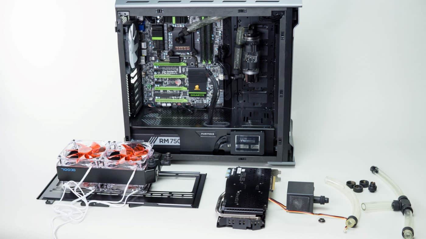
Building the Loop
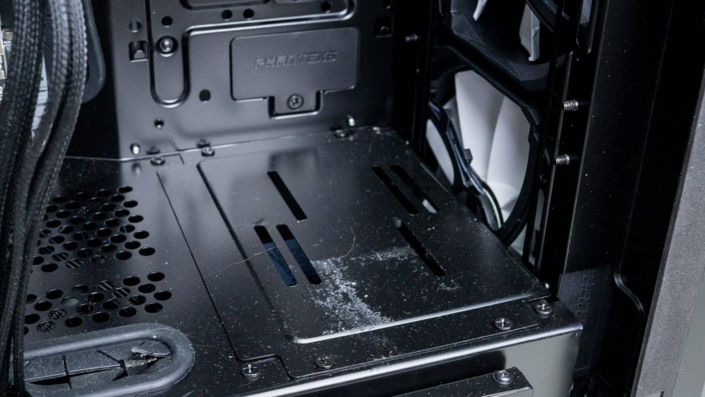
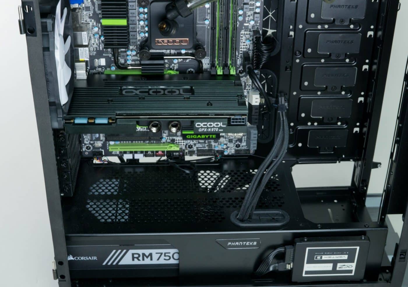
Adding two new features to our loop is going to mean changing the layout and flow around a bit. To get the space we need in the front of the case for the 360mm rad we are going to remove the cover plate at the end of the mid plate where we had the pump mounted last time. There are four screws holding it in place, after removing these we can see the lower two bay drive cages. Again we remove the screws, this time four on top and four under the case.
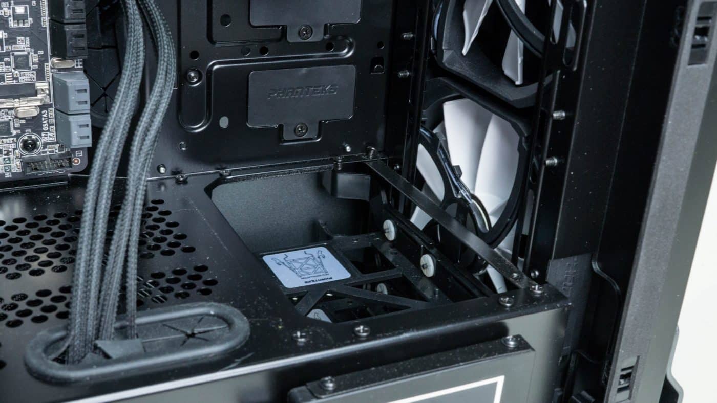
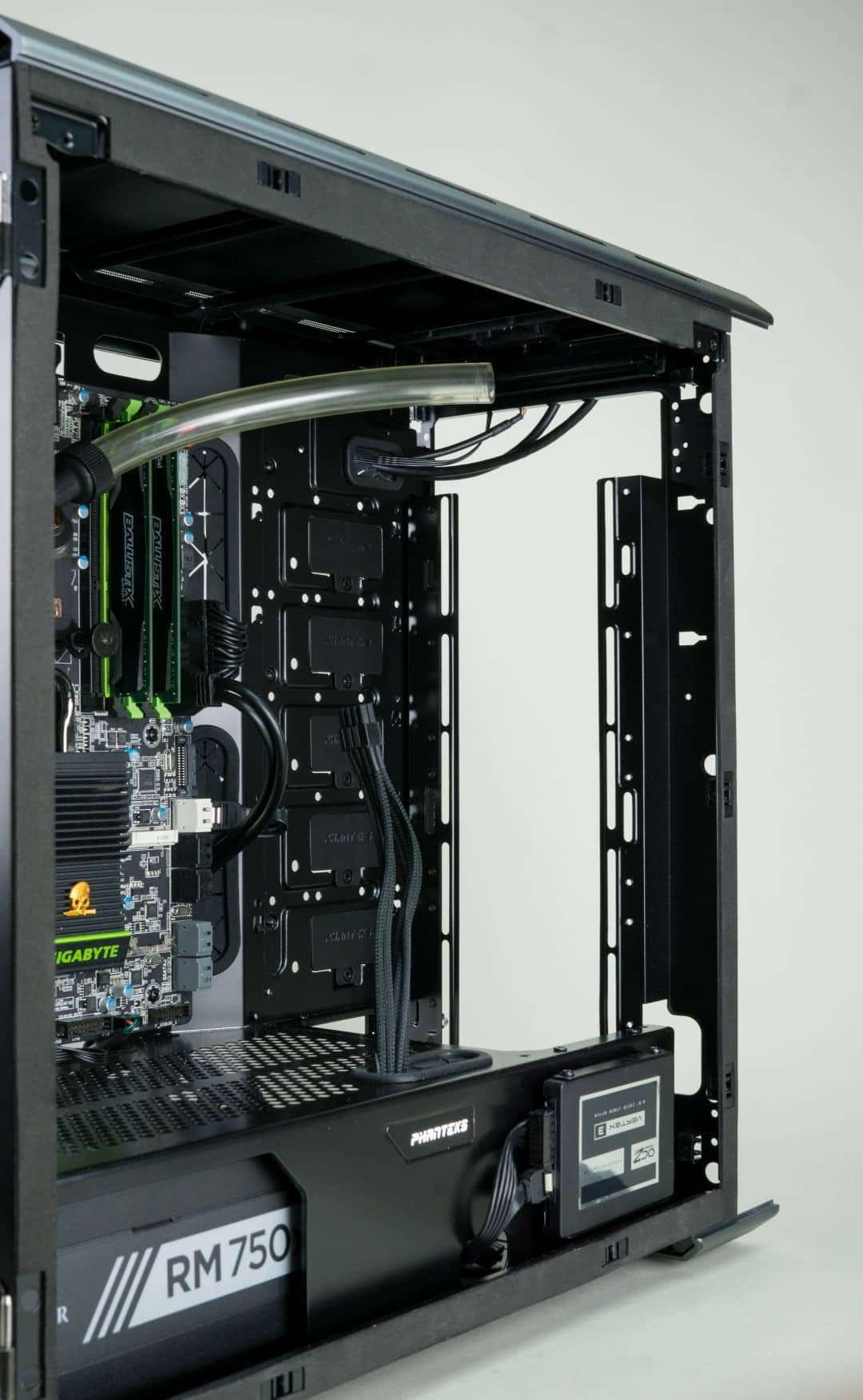
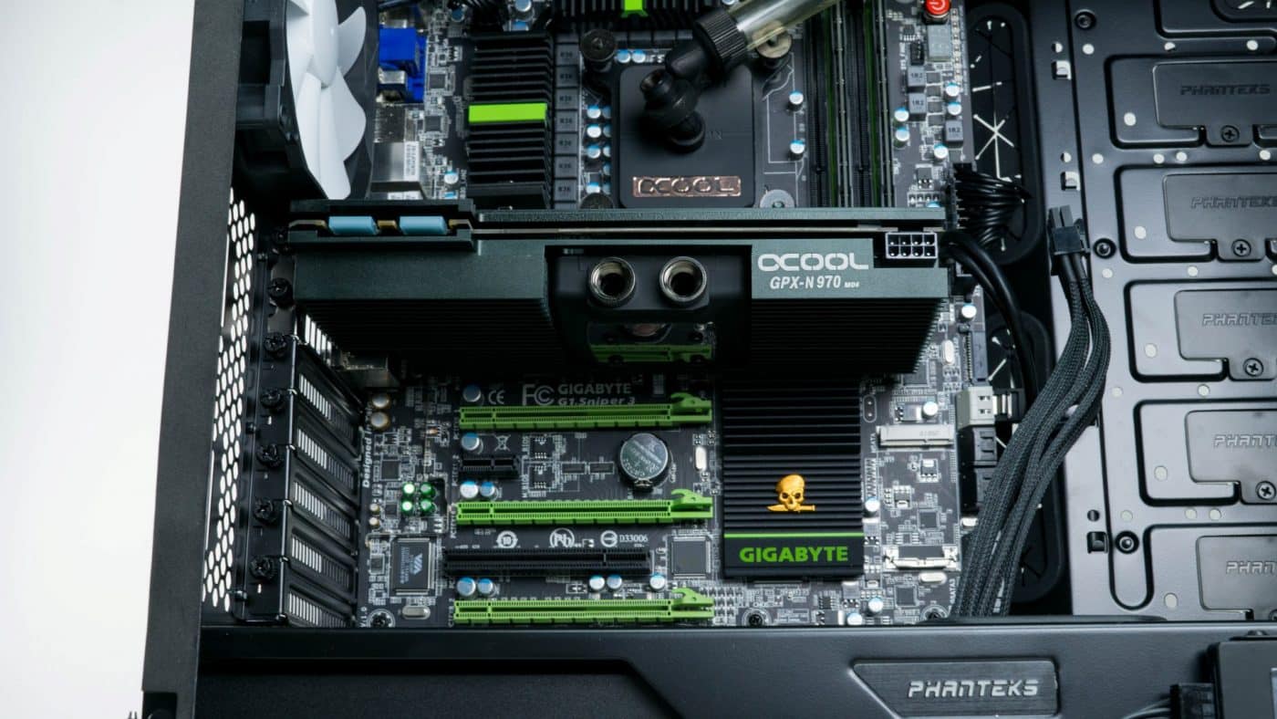
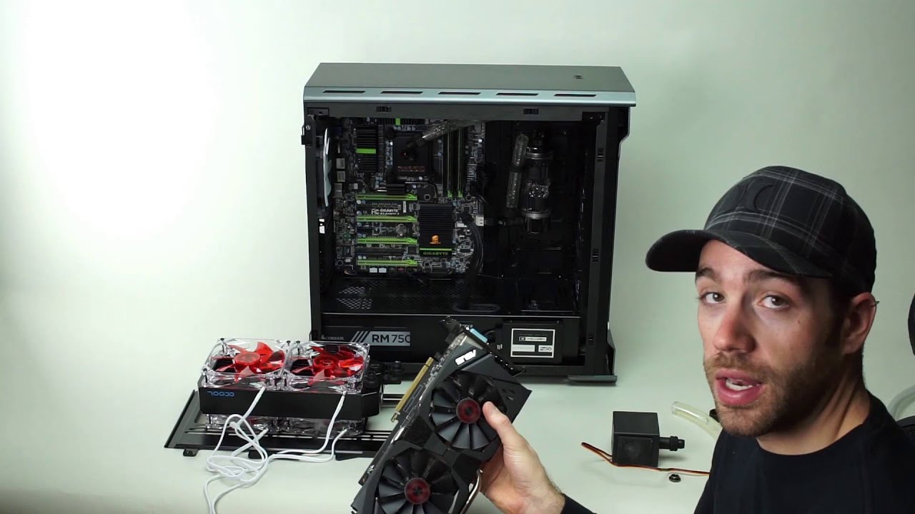
Once these pieces have been removed we pull of the front panel and fan filter to gain access to the two factory installed 140mm fans. These are easily removed and now we have a really nice open front space where we can easily install our radiator with all six fans in push/pull. We also want to install our GPU now so that we can see what kind of spacing we are dealing with. It is useful to temporarily mock things up so you can better visualize how to run your tubing.
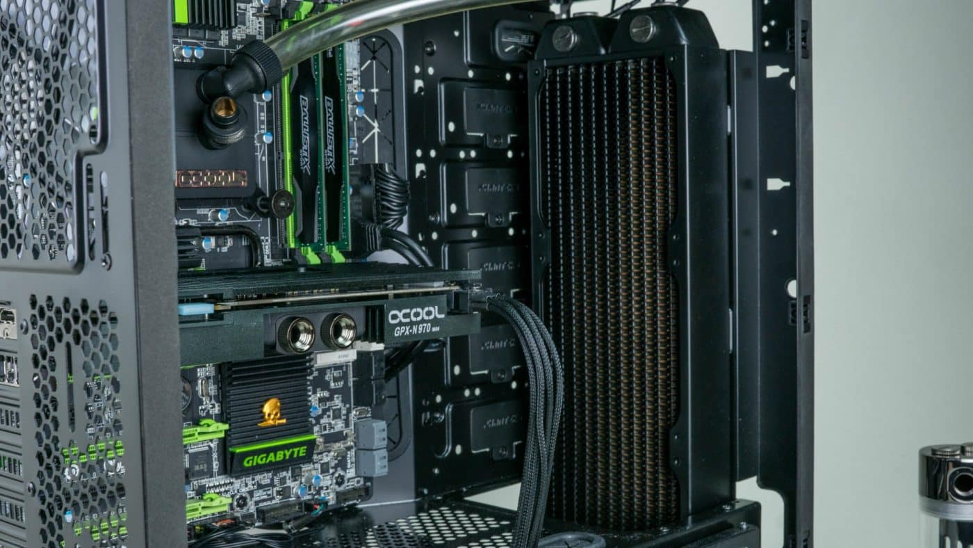
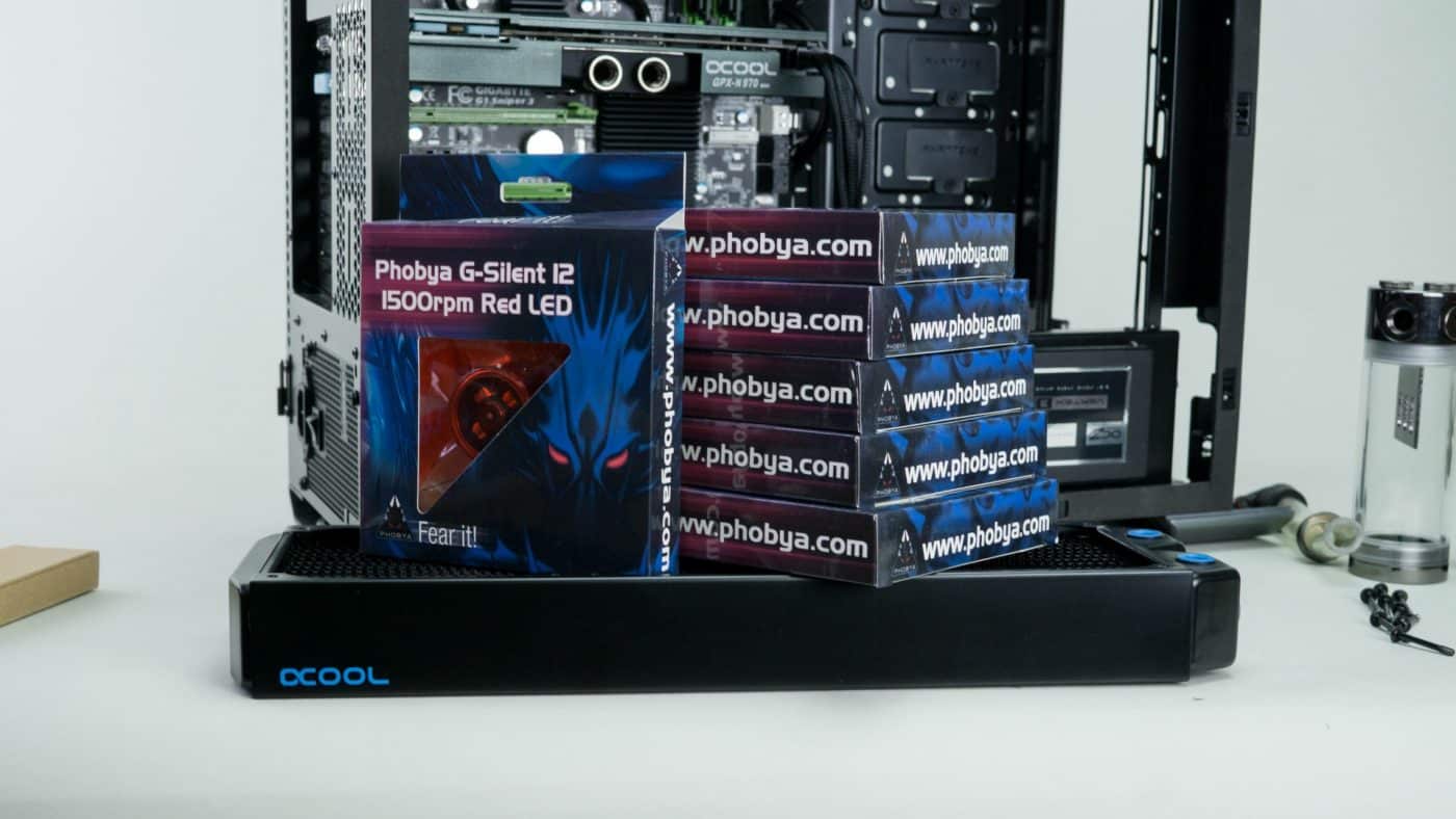
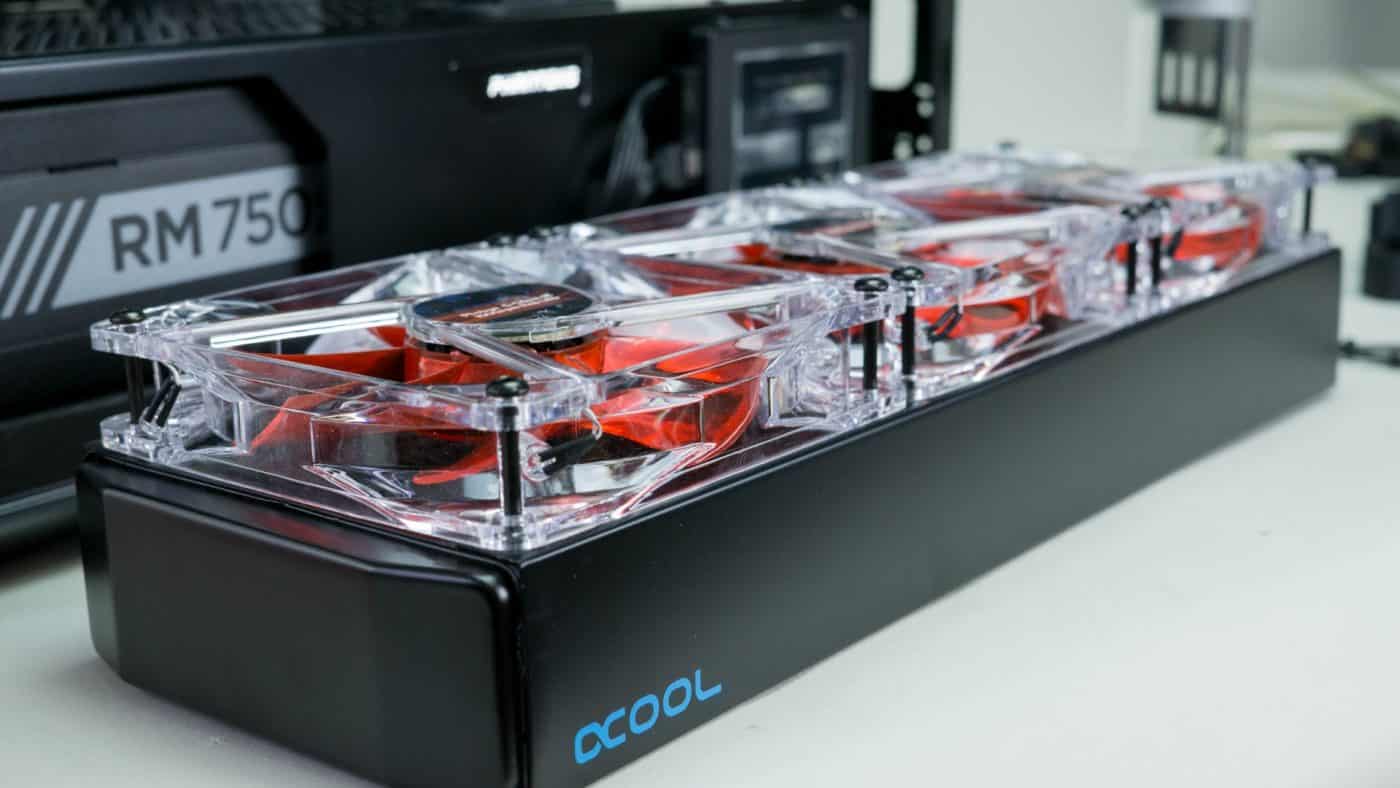
After test fitting the radiator we are sure there will be enough room for all the fans. After taking all six clear fans from their packages we install the front three oriented such that they are pulling air into the case from the front.
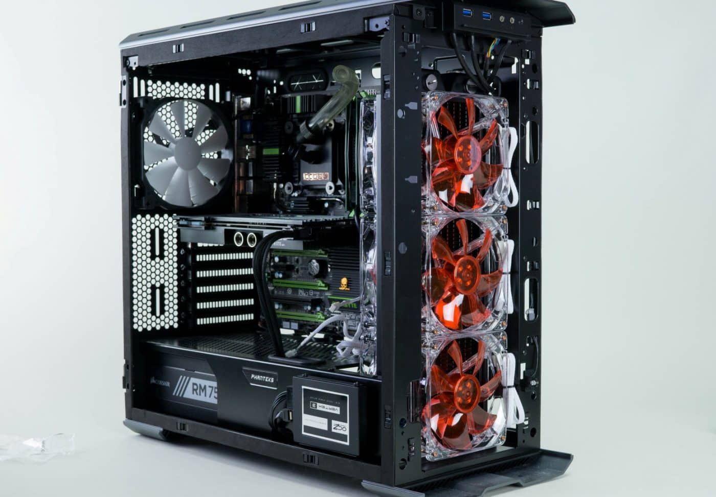
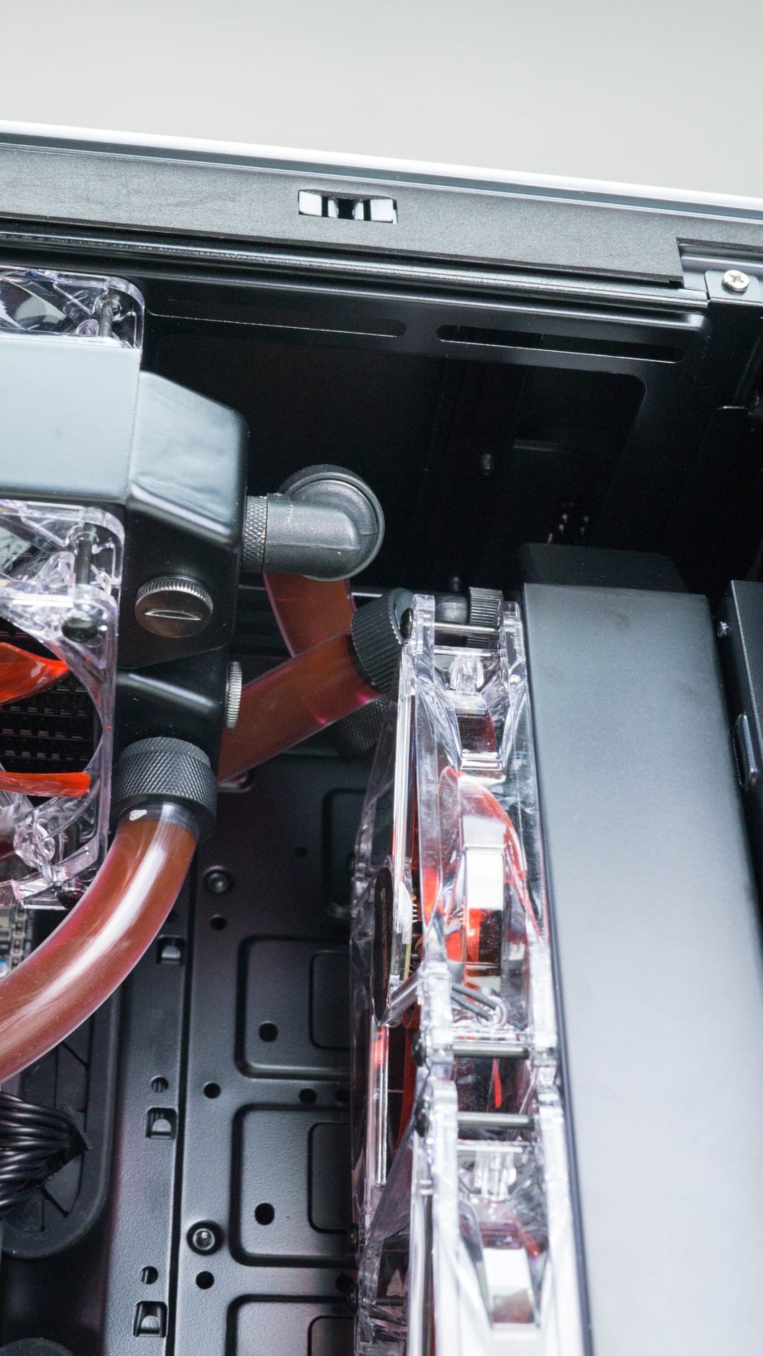
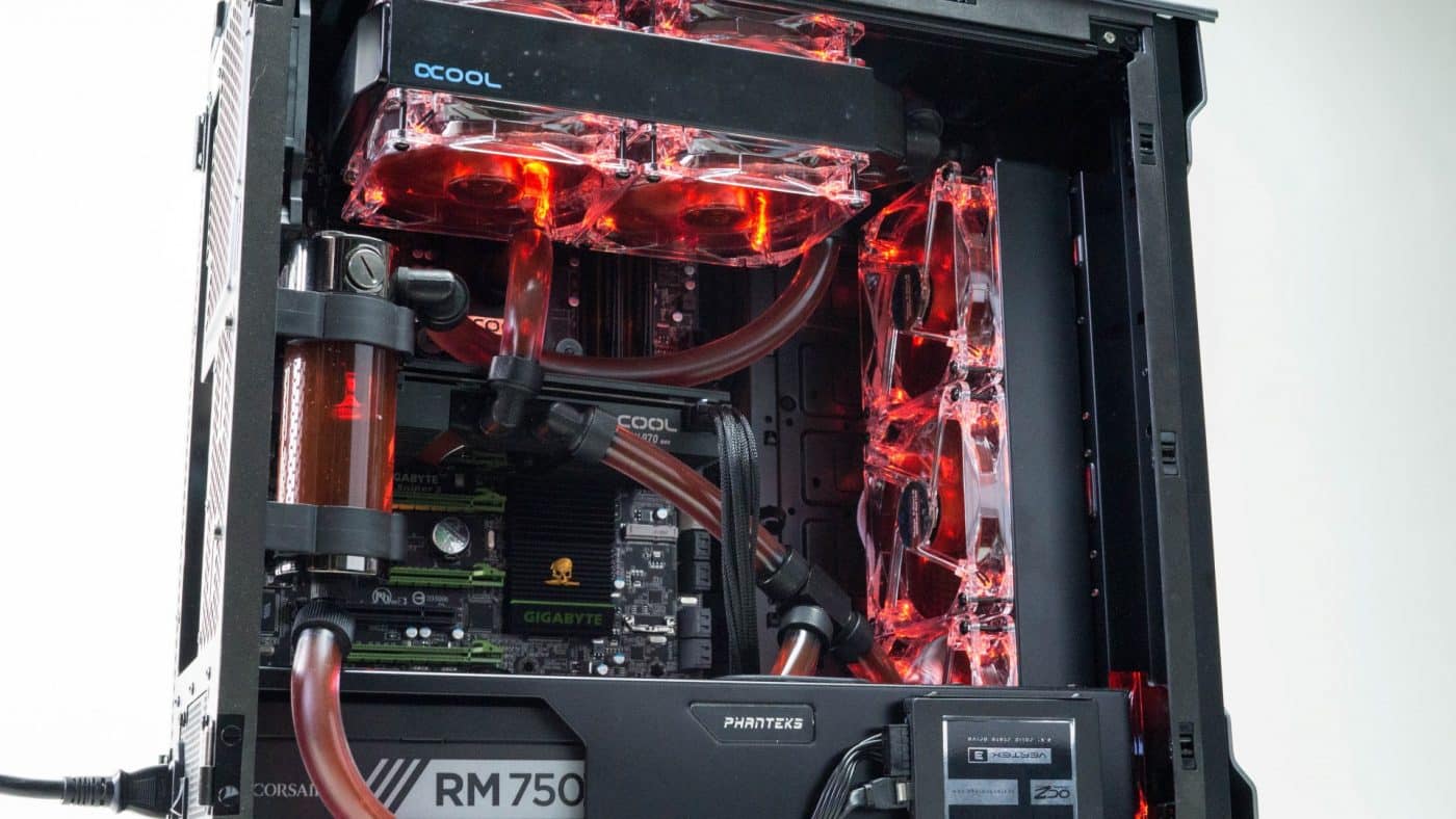
With half the fans attached we place the radiator easily into the large cut out at the front of the case and secure it with the remaining three fans. Since we won’t be removing this radiator at any point, the white sleeved three pin connectors for the fans can be passed through to the back of the case. We also slide the top rad into the channels temporarily to see how things will line up. Additionally it is pretty obvious we no longer have room for the reservoir to be mounted near the front rad so that is moved to the rear panel by the GPU. Installing water cooling can be a very creative process, remember as you go along to remain flexible with your loop layout, sometimes things must be moved around to get it to work. After testing a lot of different options to get our tubing to connect without kinking we finally settle on a layout that will work and look good.
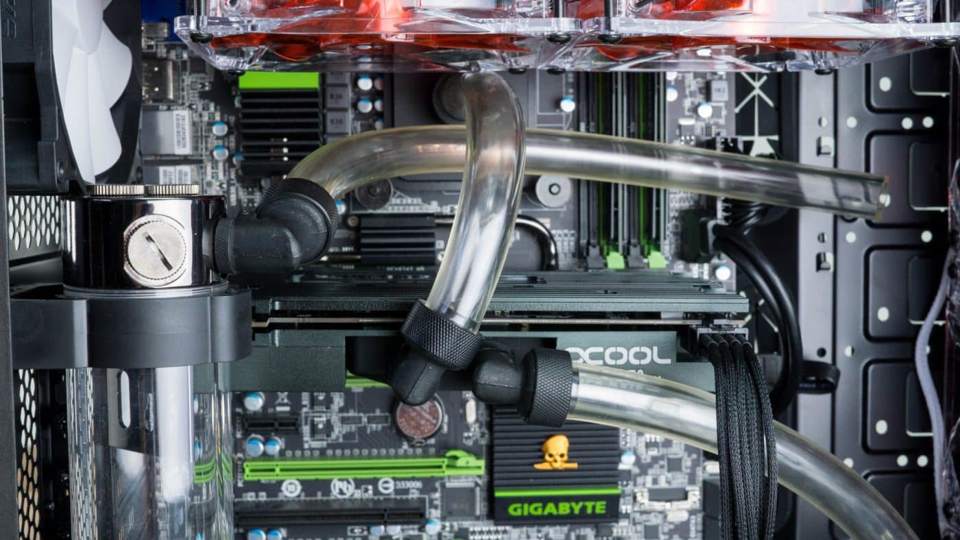
Begin connecting your tubing just as you did before, attach the tubing to one fitting, run it to the fitting it is linking and cut to fit. Don’t forget to secure with the compression fittings and be sure each fitting is screwed in tight to the port.

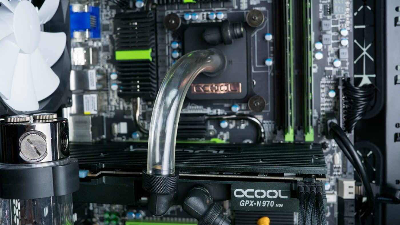
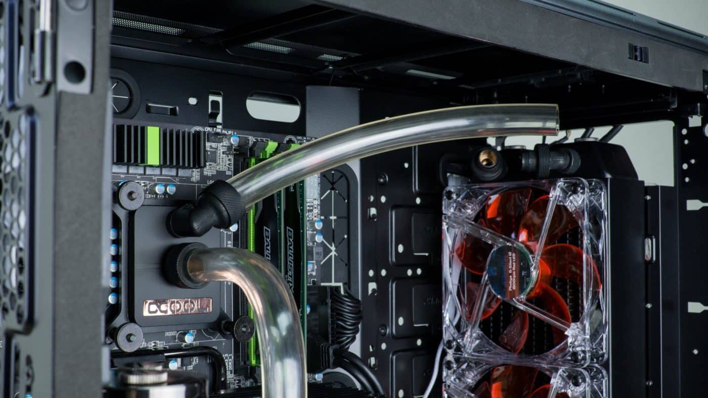
Some of your connections will be really obvious, while others might be tricky or take an odd path. Follow the old rule of less tubing looks better as often as you can, but sometimes you just have to make it work.
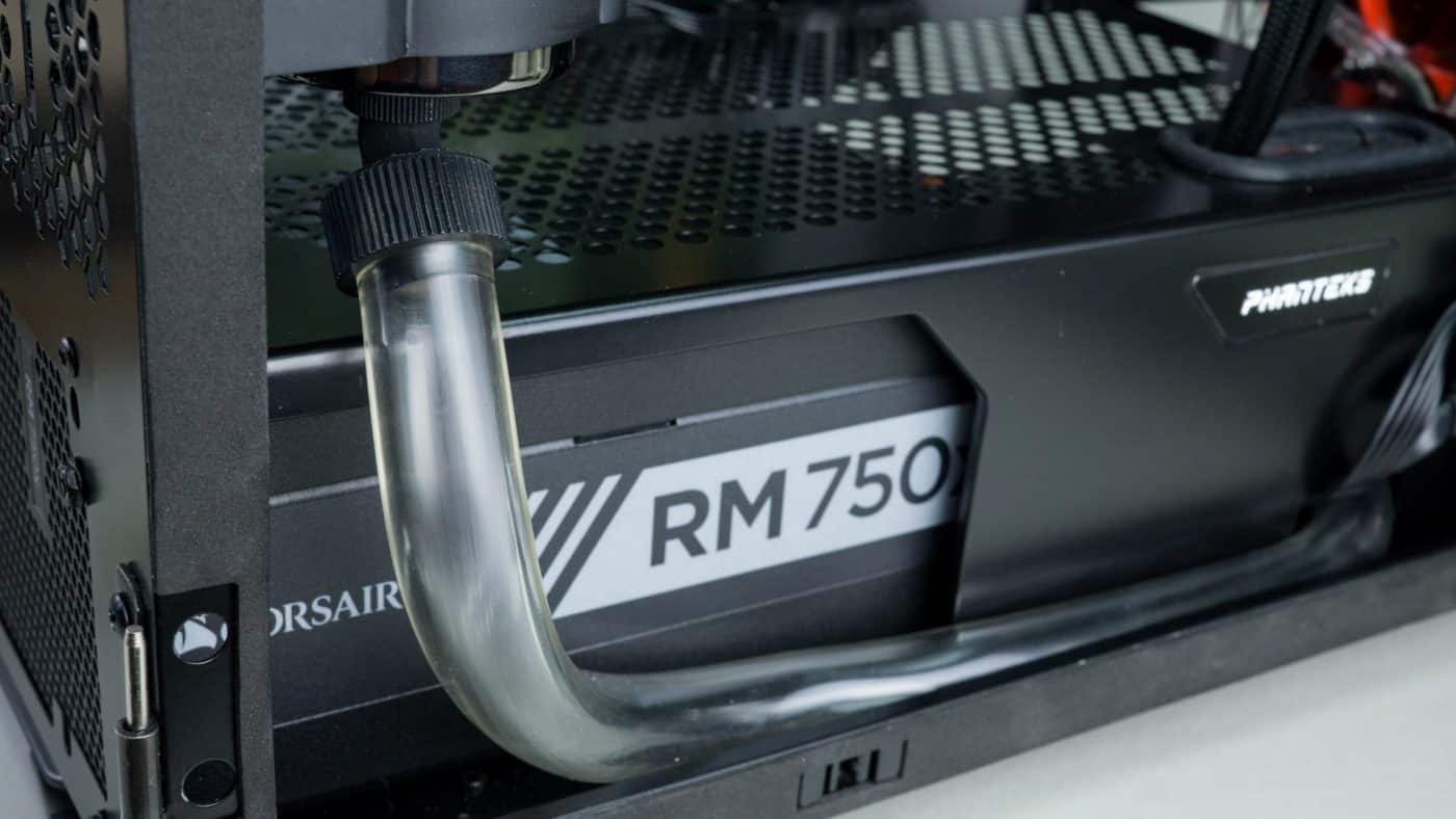
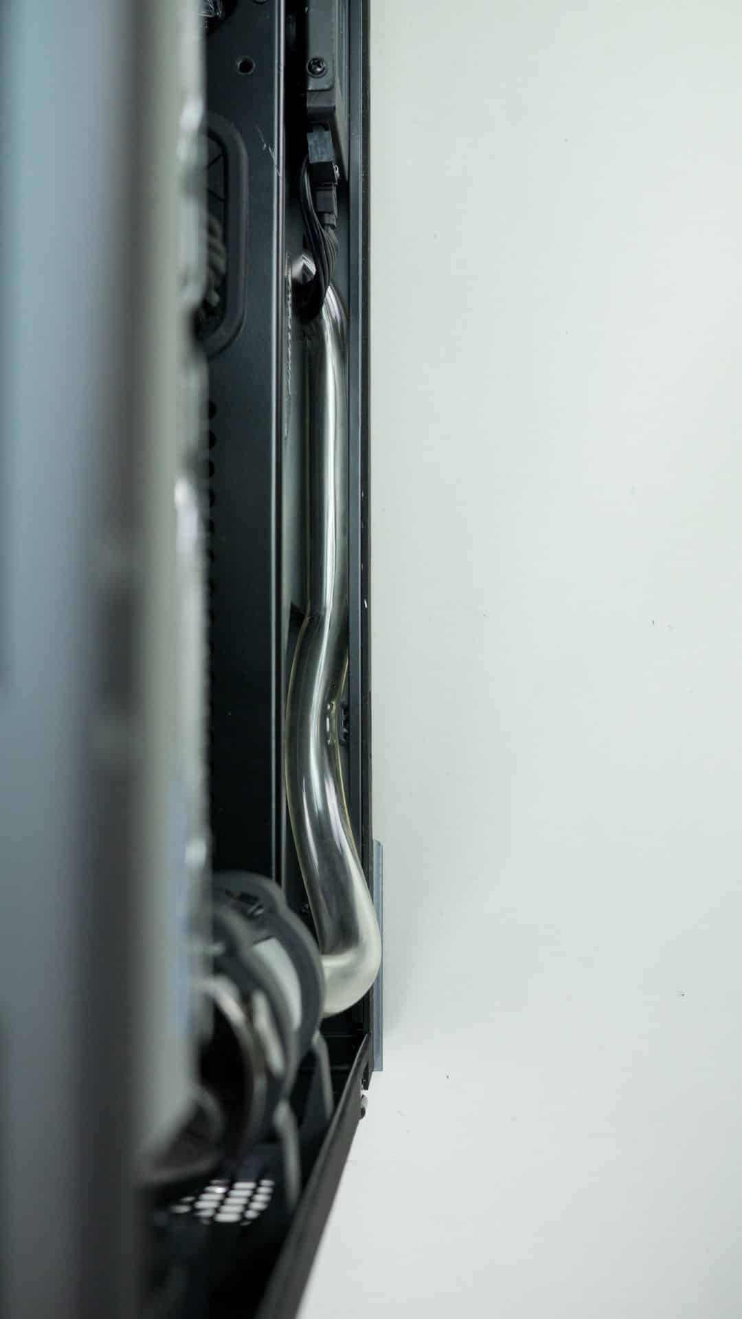

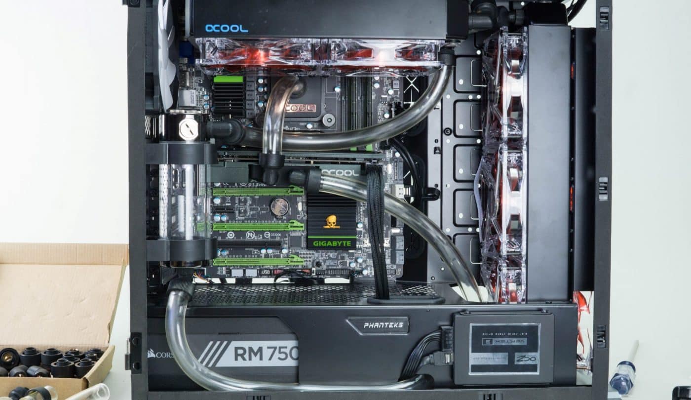
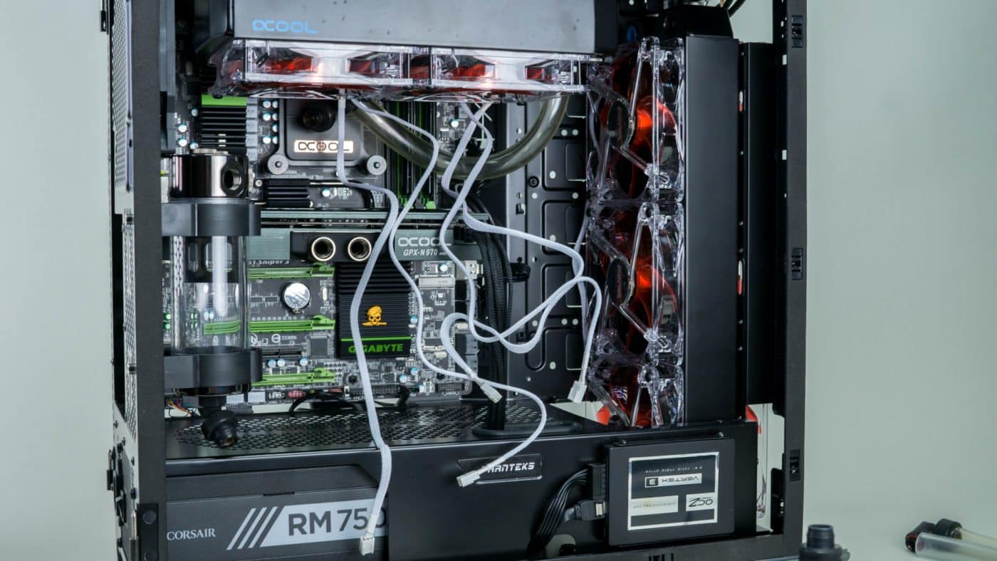
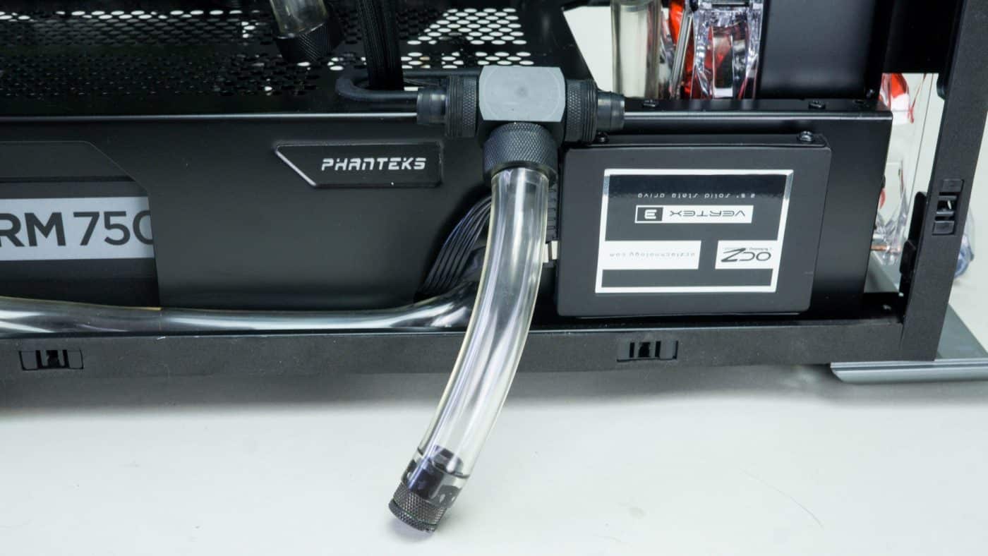
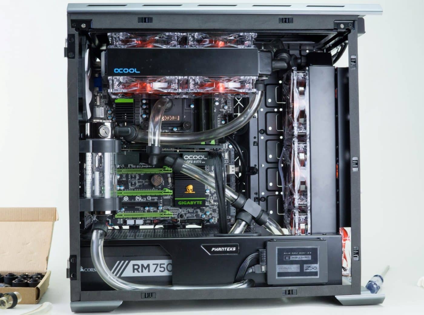
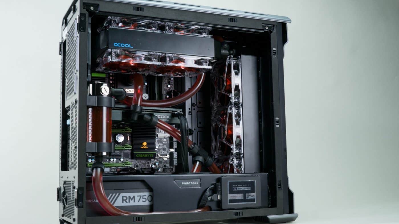
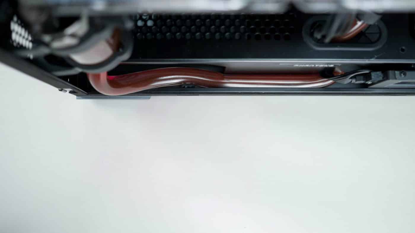
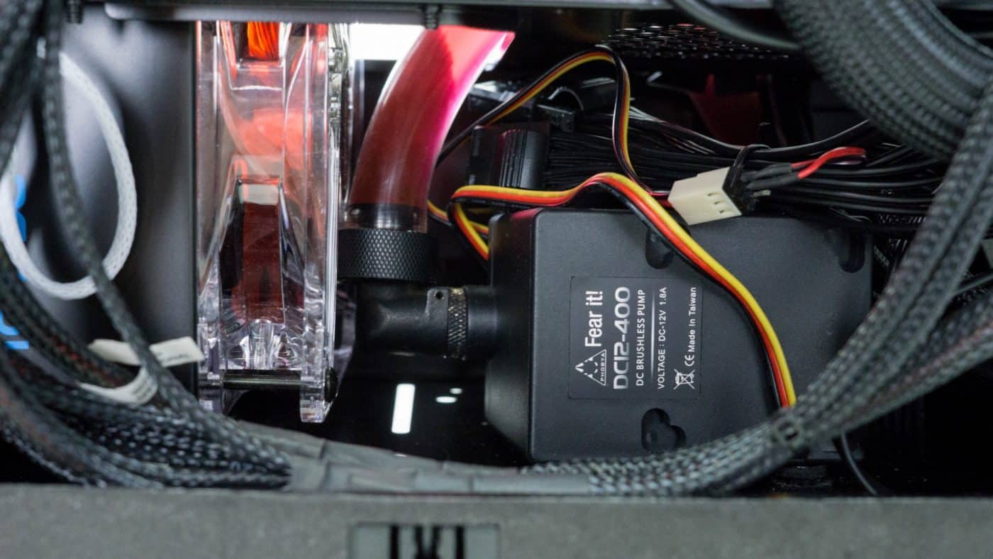
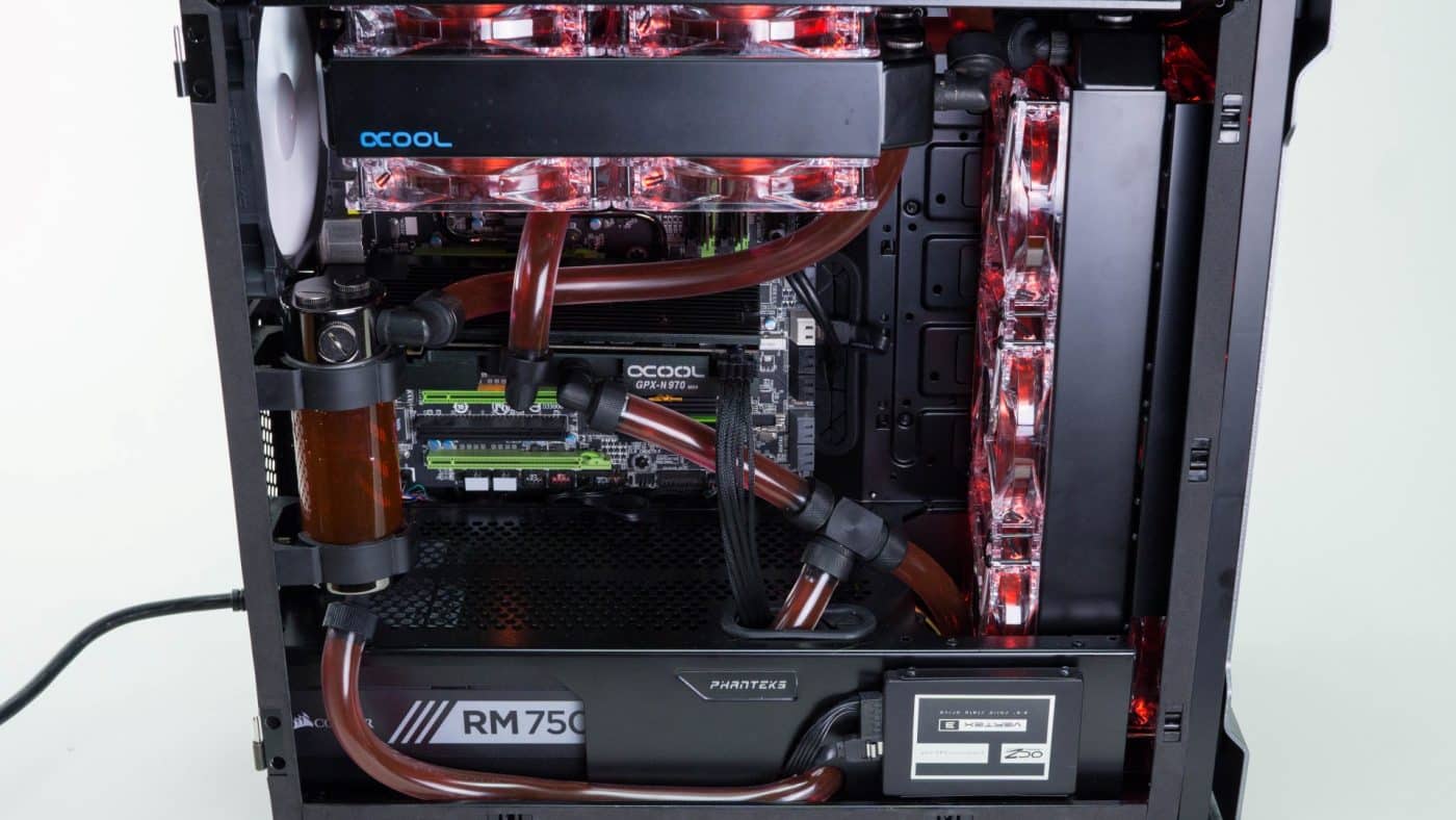
We were able to use the front pass through to feed the pump, now placed under the mid plate, and it turned out really well. The top rad does a fine job of hiding some of the tubing helping to really clean up to look of our loop. After we got everything installed we looked to add a drain line. Adding it to the loop as we went would have been ideal, but we were more concerned with getting everything connected correctly first. Fortunately there is a nice long open run of tubing connecting the pump and GPU. We cut a small section out of the middle of it and attached our T-fitting and drain line. Conveniently there is a cable pass through right in the right position for us to run the drain line through and hide it out of sight a bit.
After this the only thing to do is to fill the loop; this time we will be adding some red dye as well.
While filling the loop we actually had a couple leaks. This happens. Don’t panic. Move quickly and have your paper towel handy ready to fix any issue. For us it was simply a couple of fittings we didn’t get tightened all the way into their ports. Without draining the loop we tightened those two fittings and we were good to go. If it happens to you, be sure to wipe up all the leaked drops before actually powering the rig up, but otherwise a small leak really isn’t a big deal.
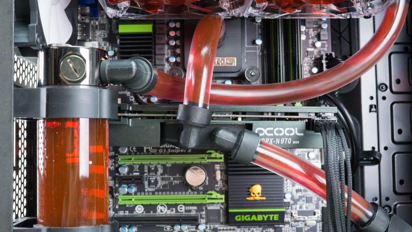
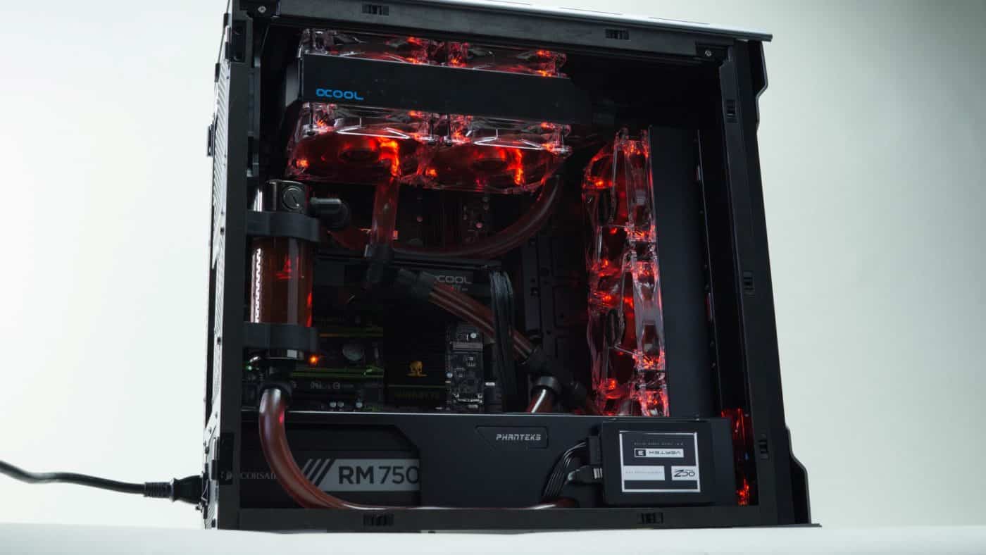
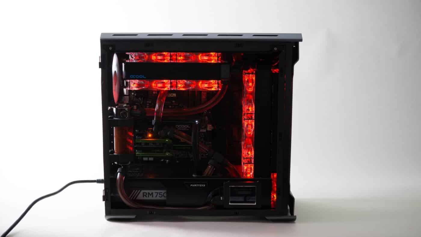
We really like the way the ThinkComputers rig turned out, the red dye and clear tubing really matching nicely with those clear bodied red blade equipped Phobya fans.
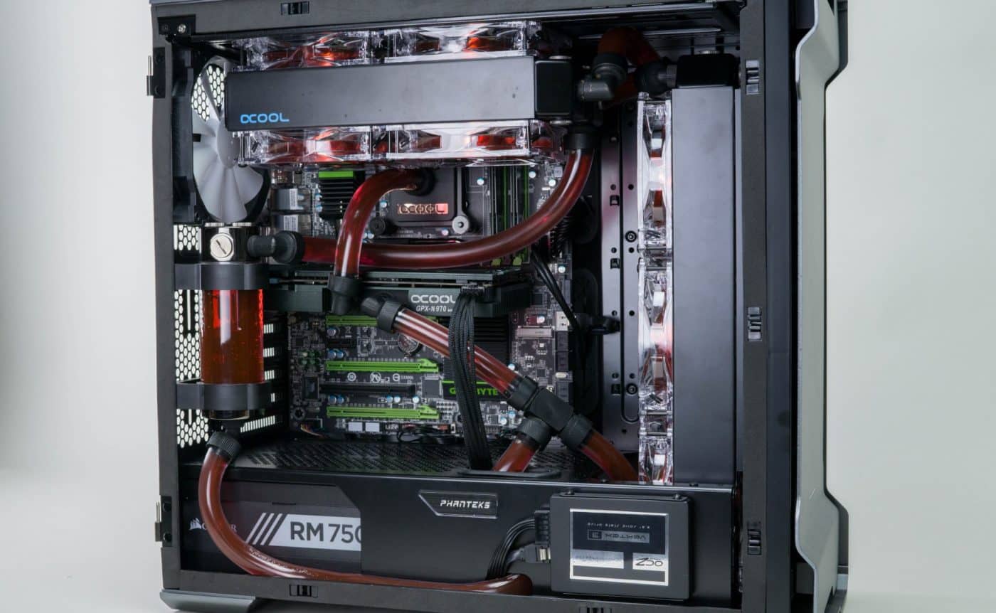

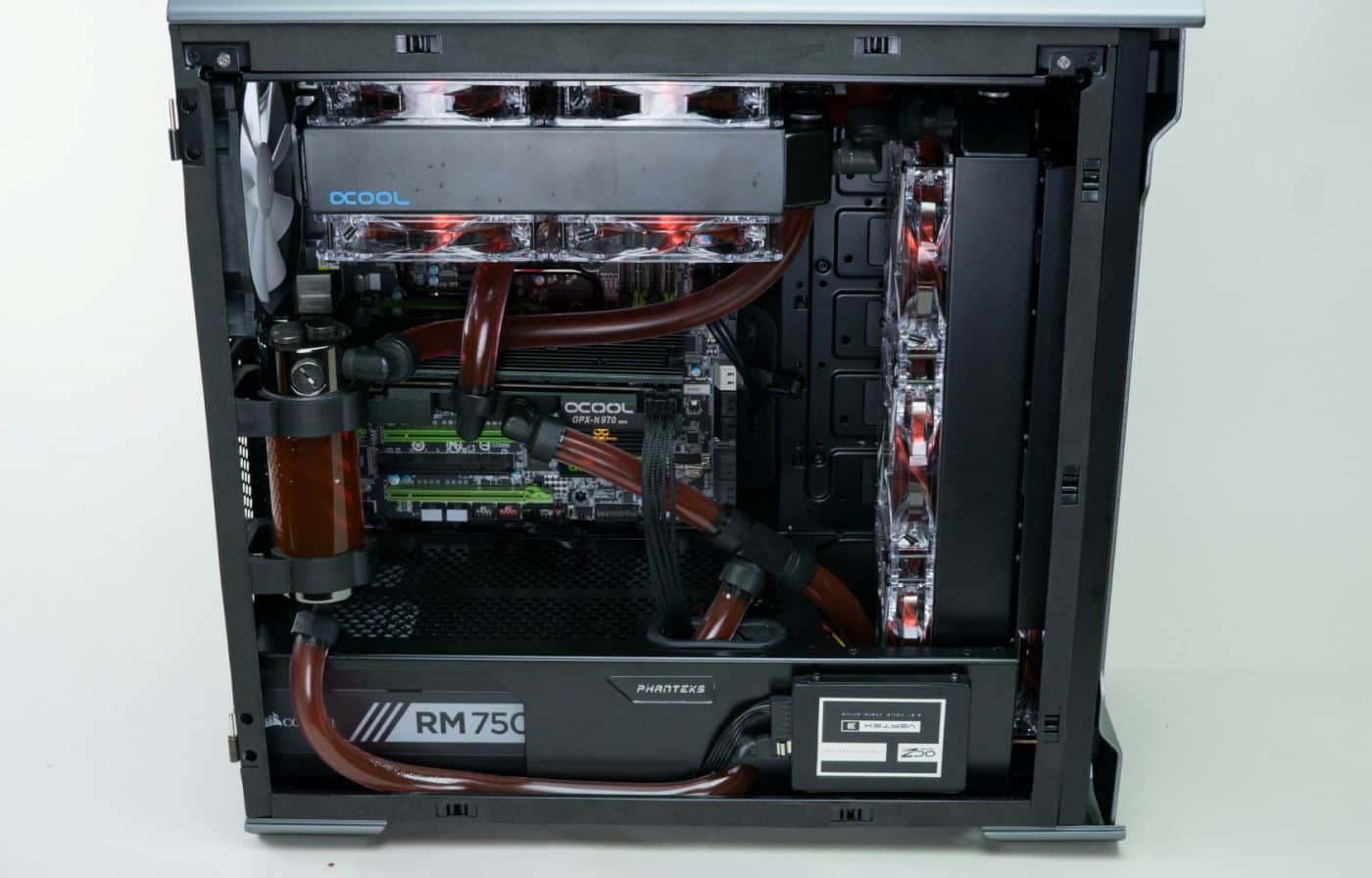
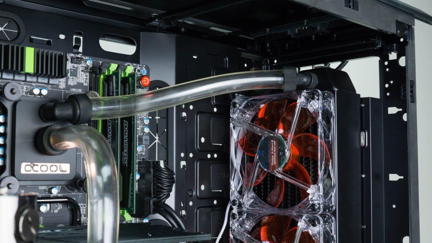
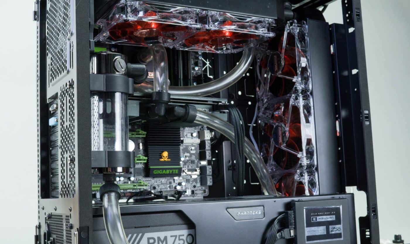
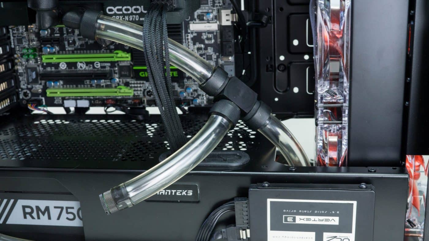
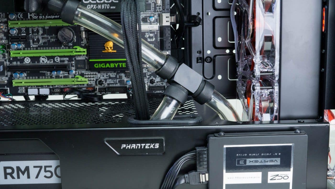
As you can see from our rad to rad connection sometimes you really have to get creative and be persistent to make your loop work. It’s also helpful to have some extra angled fittings that you can use to try different things out.
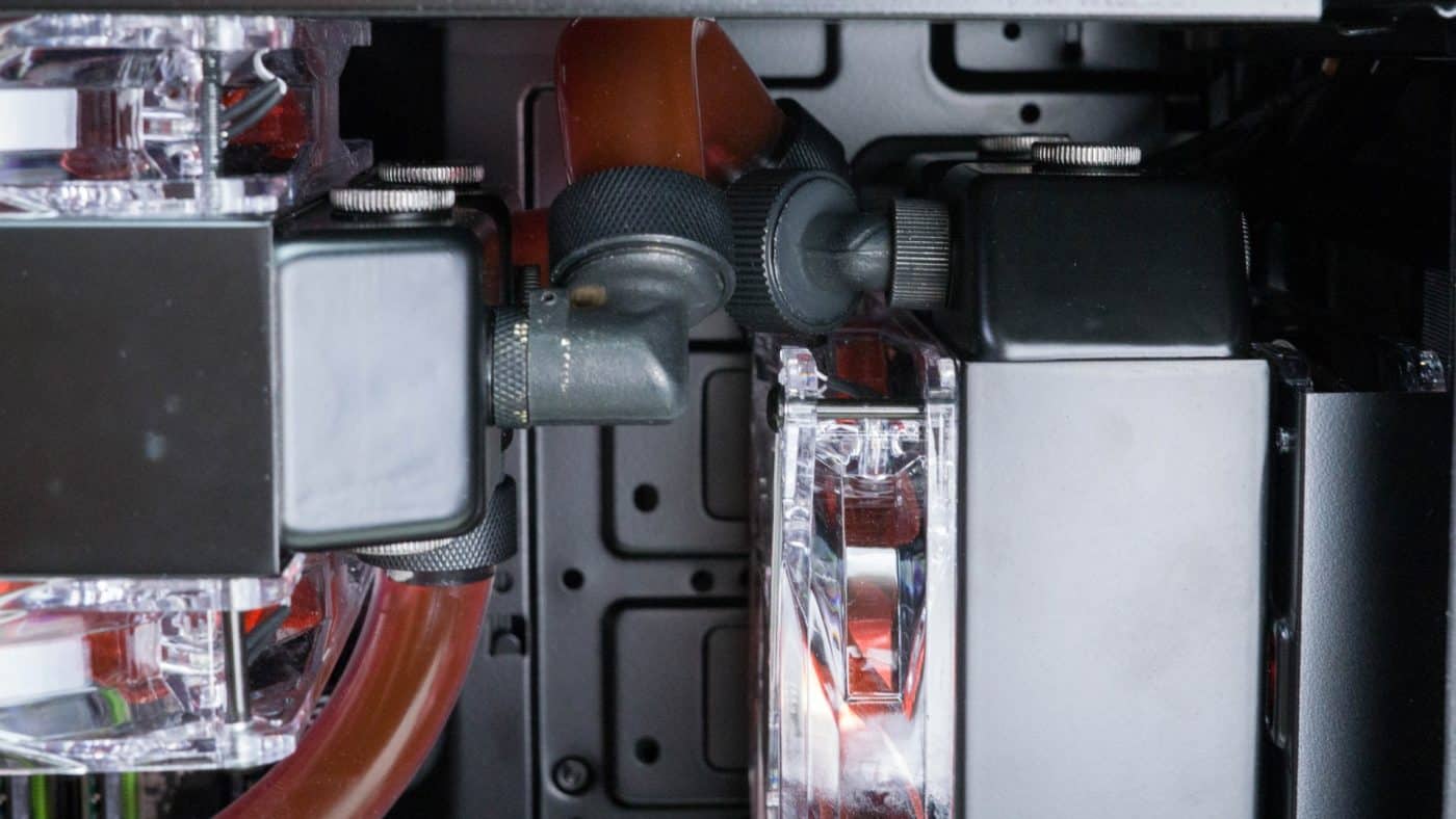
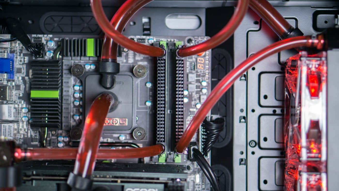
A lot of the loop has an intricate feel with fittings and tubing really running around and through each other.
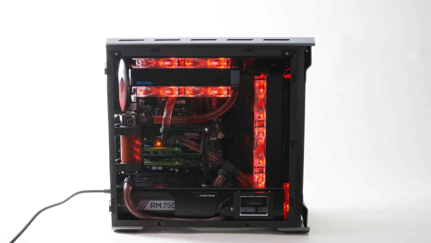
Fully powering the rig and turning on the red LEDs really adds just that extra little bit of panache to the interior of the case really setting everything off.


When talking about upgrading/expanding a water loop, you should mention quick-disconnect fittings.