Gigabyte X99P-SLI Overview
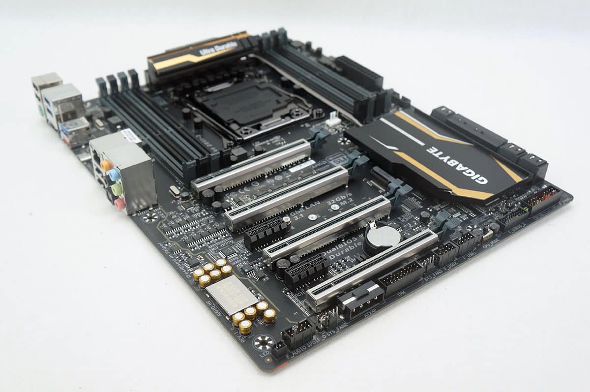
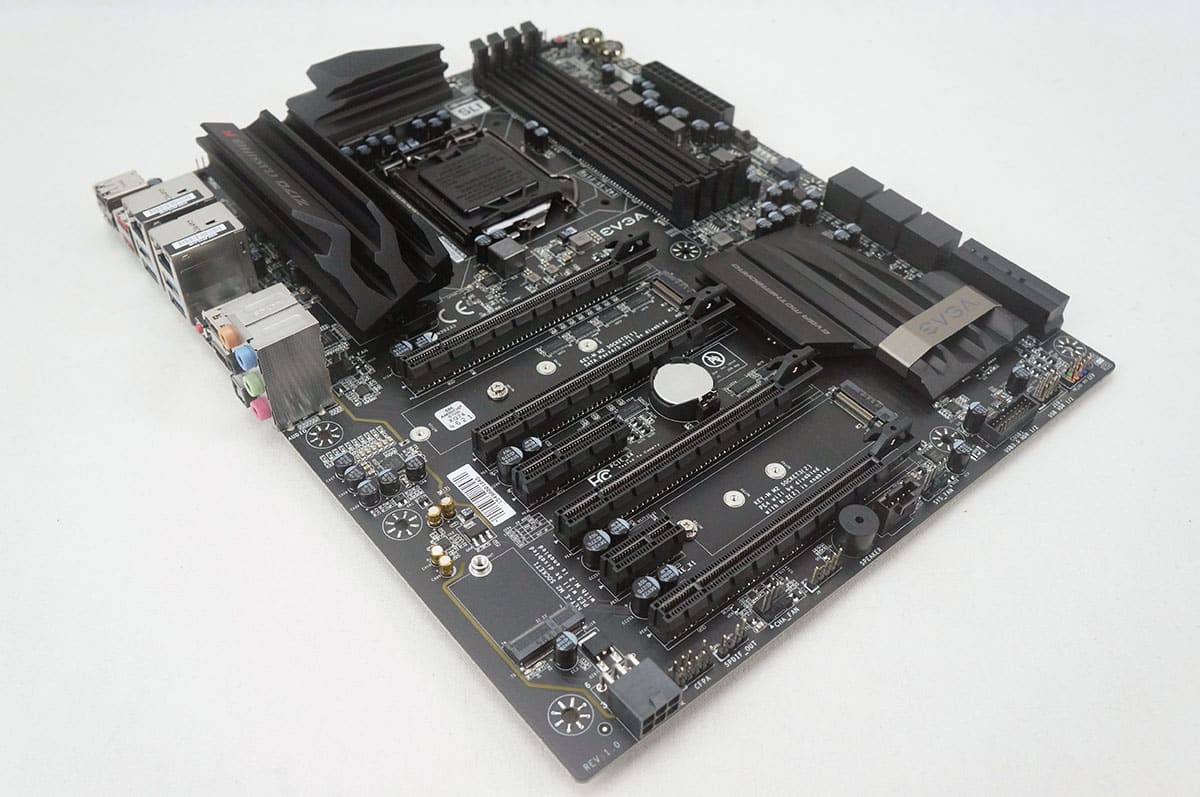
Gigabyte keep their same black and gold color design that we’ve seen with their other Ultra Durable boards in their X99 line. So you have a nice black PCB with gold accents on the heatsinks. There is a heatsink on the power delivery components as well as the PCH. They are connected by a large heatpipe.

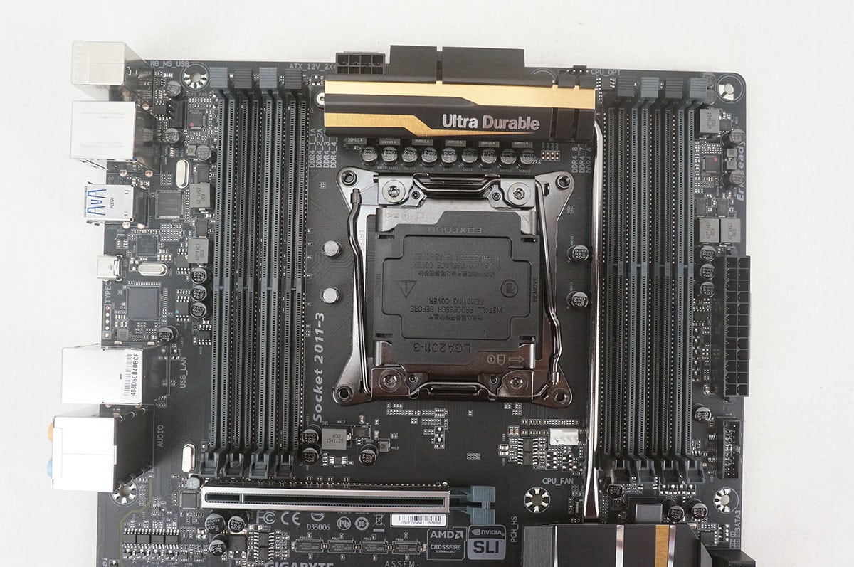
Starting towards the top of the board we have the Intel LGA2011v3 socket, which of course supports Intel’s latest Haswell-E HEDT processors. This board features an all digital power design that makes use of IR Digital PWM and IR PowIRstage ICs. These 100% digital controllers offer incredible precision in delivering power to the motherboard’s most power-hungry and energy-sensitive components. Flanking the CPU socket on each side is four DDR4 DIMM slots (a total of 8). These DDR4 slots are color-coded for quad channel operation and support up to 128GB of DDR4-3333 memory. The 8-pin EPS connector is located right above the heatsink on the power delivery components. The CPU fan header is located below the CPU socket on the right side. There is also an optional CPU fan header above the CPU socket and a 4-pin fan header near the rear I/O.
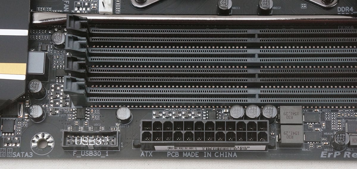
Moving over to the right side of the board we have our 24-pin ATX power connection and a USB header.
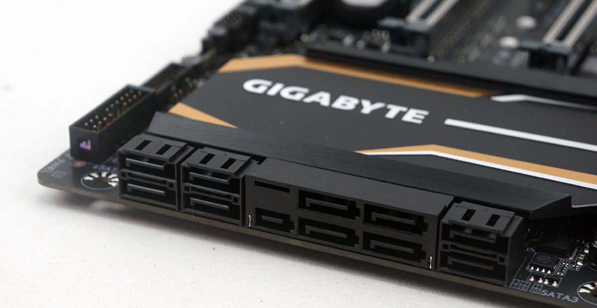
Moving down the board to our storage connections we have eight SATA 6GB/s ports and a single SATA Express port. Keep in mind if you do not want to use the SATA Express port that opens up two more SATA 6GB/s ports giving you a total of 10 SATA 6GB/s ports.
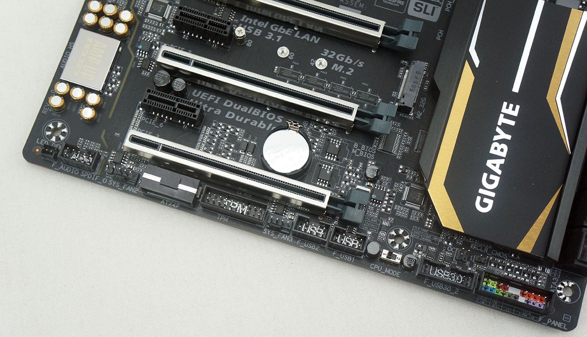
At the bottom of the board is where you will find the rest of the your connections, headers and switches. From right to left you have front panel connections, a second USB 3.0 header, CPU_Mode switch, two USB 2.0 headers, a 4-pin fan header, TPM header, Molex power connection, another 4-pin fan header and HD audio header. Right above the front panel connections is a header to clear your CMOS. It would have been nice to have a button to do this rather than a header.
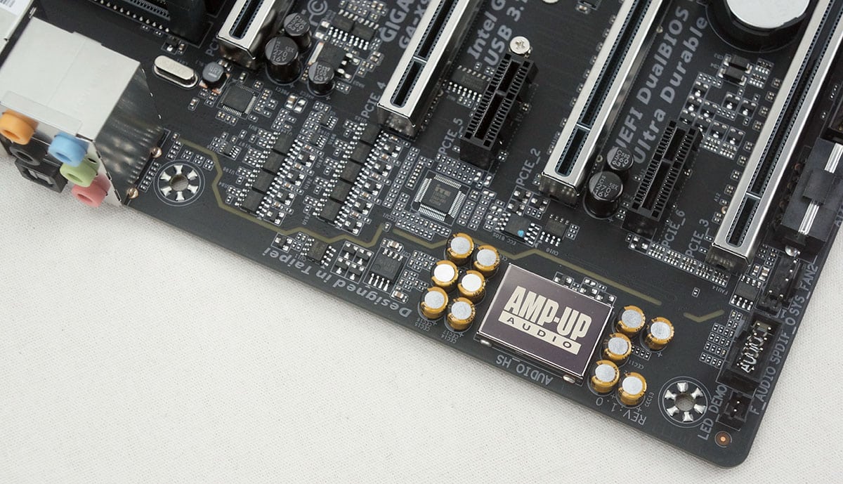
Along the far end of the motherboard we can see Gigabyte’s AMP-UP audio solution. This gives you Realtek ALC1150 115dB SNR HD Audio with a built-in Rear Audio Amplifier. The design puts the left and right audio channels on their own PCB layers and you have high-end Nichicon audio capacitors. You will also notice the PCB isolation of the entire audio section, which has a LED trace.
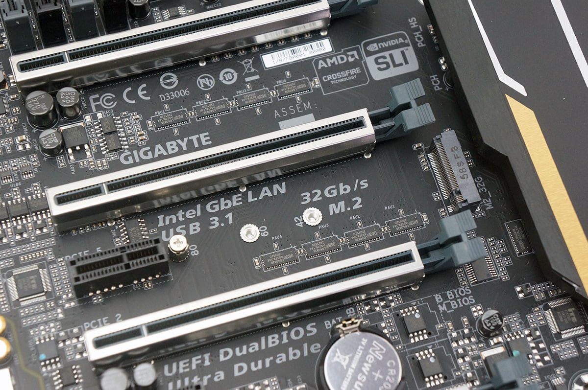
When it comes to expansion slots you have four PCI-Express 3.0 x16 slots and two PCI-Express x1 slots. Slots PCIE_1/PCIE_2 will always operate at x16 mode and slots PCIE_3/PCIE_4 will always operate at x8 mode. This board supports 4-way SLI and CrossFire setups. You will notice the PCI-Express ports have the metal shielding on them. This one piece stainless steel design will reinforce the PCIe connectors to provide the extra strength required to support heavy graphics cards.
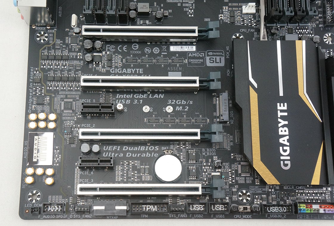
In between the second and third PCI-Express slots you will find an M.2 slot. This is a PCI-Express 3.0 x4 slot so you have 32 Gb/s of available bandwidth and NVMe support.
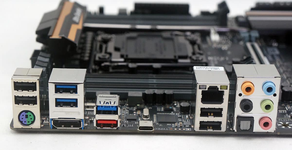
Moving to the rear I/O on the board from left to right we have two USB 2.0 ports, a combination PS/2 port, three USB 3.0 ports, a DisplayPort-in port, two USB 3.1 ports (one Type-A, one Type-C), Gigabit Ethernet, two more USB 2.0 ports, and audio connections. The two USB 3.1 ports are powered by Intel’s USB 3.1 controller which uses four PCI-Express 3.0 lanes which gives you up to 32 Gb of bandwidth. The Type-C connector can be used for a bunch of different types of accessories, even displays. Gigabyte includes DisplayPort cables to connect your graphics card to the DisplayPort-in port on the motherboard so you can use a Type-C display.


Dear thinkcomputers.org,
I do run an ad blocker, because I am sick and tired of asshole websites such as yours trying to sell my shit I DONT FUCKIN NEED! NO I DONT NEED A FUCKIN PENIS ENLARGEMENT, already have complaints that its to big. No i do not need a fuckin over priced electric car, i prefer my gas guzzling monster truck that eats those electric shits for breakfast. NO i dont give a rats ass about your opinion on anything.