Maximus VI Gene Motherboard Overview
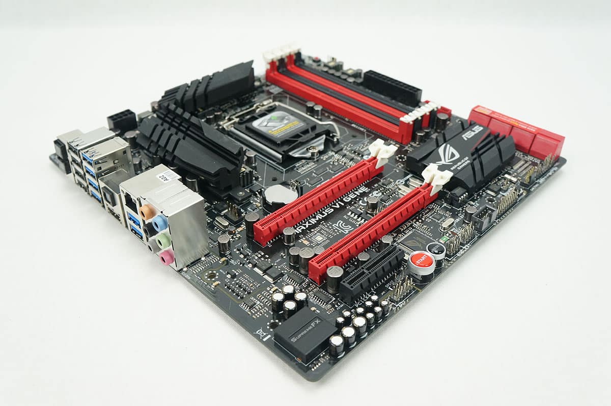
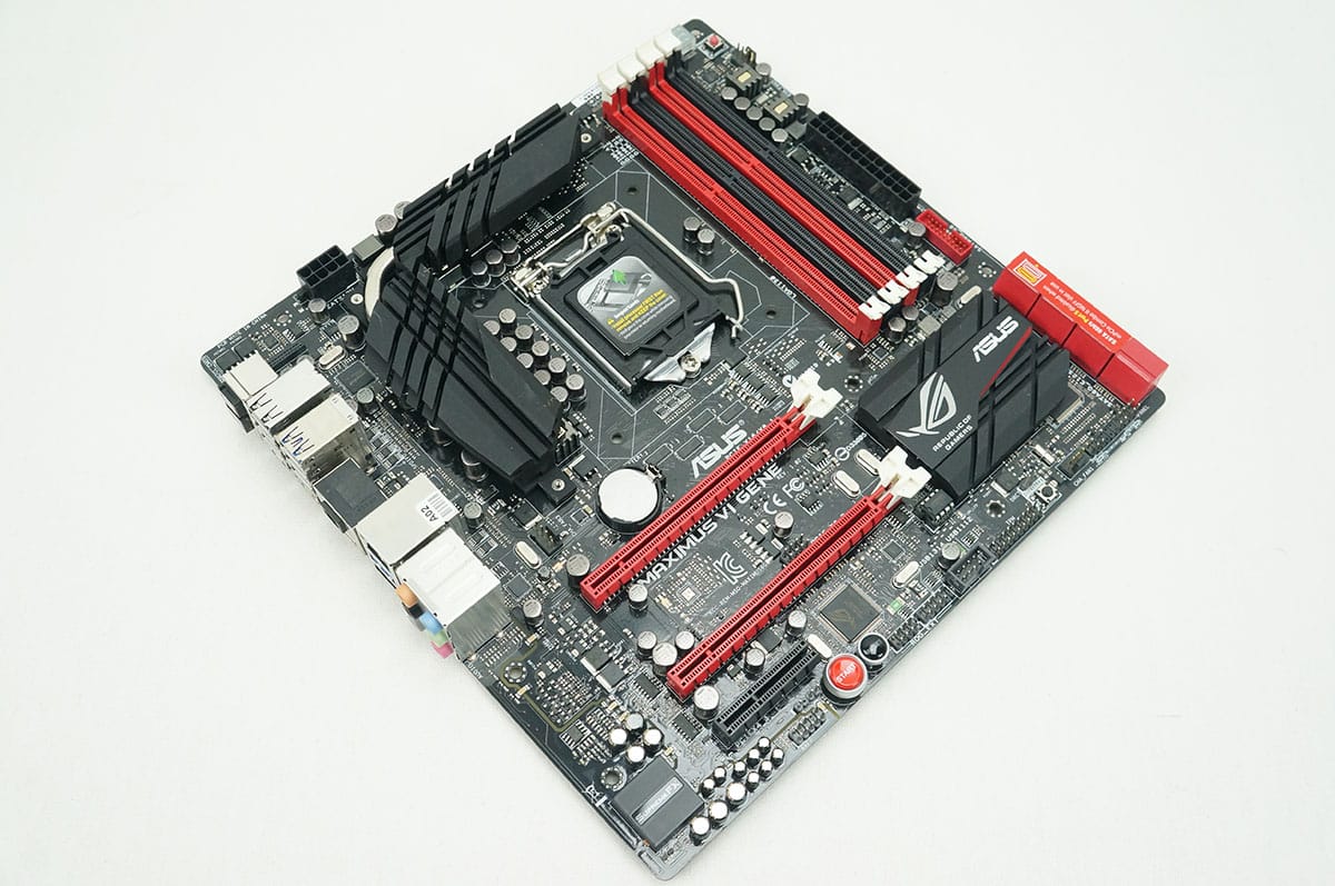
The Maximus VI Gene Motherboard is of course a Micro-ATX motherboard so it is a bit smaller than your typical ATX motherboard. It has the same styling that we have seen on many ASUS Republic of Gamers motherboards with an all black PCB and red and black accents. There a large aggressively-styled heatsinks on the power delivery components and the PCH. The heatsink on the PCH has the Republic of Gamers logo on it.
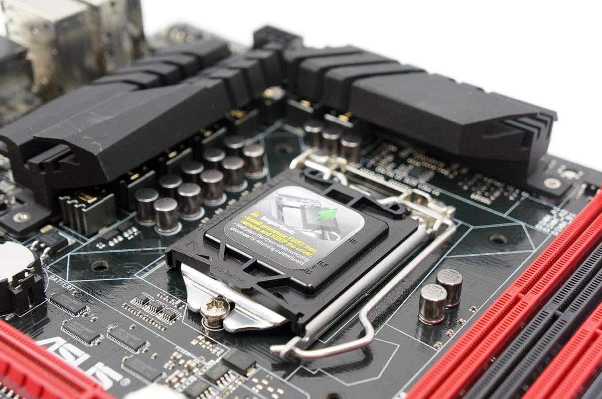
Taking a look at the CPU socket and power delivery components this motherboard has the LGA1150 socket meaning it will support Intel’s 4th generation Haswell processors. The Maximus VI Gene features an 8 + 2 all digital power phase design, that is 8 phases for the CPU and 2 for the memory. ASUS calls their power delivery system Extreme Engine DIGI+ III and it is made up of some pretty high quality components. First you have NexFET MOSFETs that have 90% greater efficiency under normal operation. There also also 60A BlackWing chokes that are an ROG exclusive and as the same suggests support up to 60A, have 3-5C lower temperatures and have a gold-treated coating for minimal-loss power delivery. The board also features 10K black metallic capacitors that offer a 20% greater low temperature endurance and 5X longer lifetime usage. As I said earlier there are two large heatsinks keeping your power delivery components nice and cool and they are connected via a flat heatpipe.
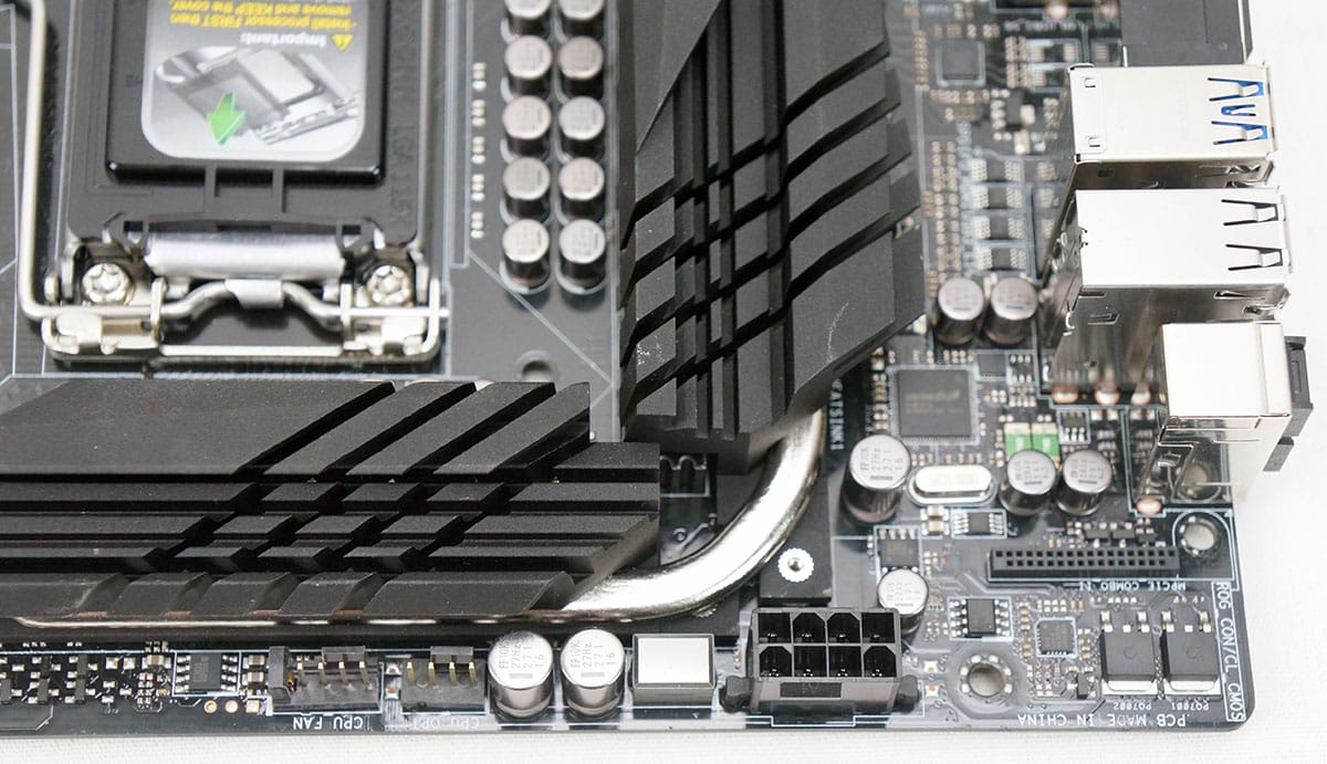
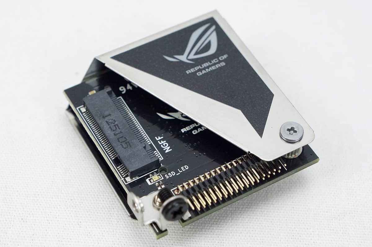
Moving up to the top corner of the motherboard we can see where you can install the mPCIe combo card. The card is completely optional meaning you don’t have to use it if you don’t want to. Power comes to the board via an 8pin EPS connector. Moving along the top of the board there are two 4pin fan connectors, one for your CPU fan and the other is for a second optional CPU fan. This is great as you may want to control the two fans that are on your CPU cooler independently. You will notice a little tab on the end of the CPU fan connector. This is actually a detection latch that will determine if you have a 3pin or 4pin fan connected. This way you can use ASUS’s software to control this fan no matter if its 3pin or 4pin. Previously you were only able to do this with 4pin fans.
The mPCIe Combo card adds great expandability and functionality to this card. It adds PCI-Express 2.0 plus USB 2.0. This is great for adding WiFi and Bluetooth modules to make your system wireless. On the other side of the card is an M.2 slot for NGFF solid state drives. These little drives are perfect for an OS drive or caching drive.
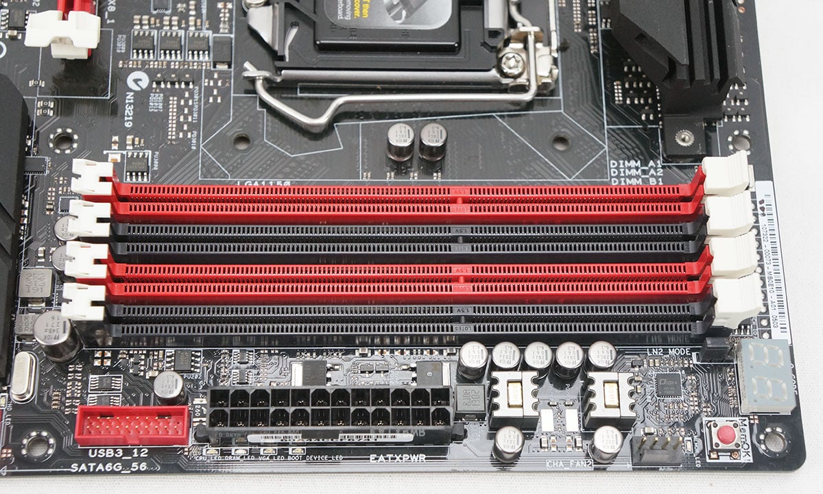
On to the side of the board we can see 4 DIMM slots that support up to 32 GB of DDR3-
3000 (OC) in dual-channel configuration. These slots are color-coded to denote channels and on the bottom they do not have locking latches. This is to make swapping out your memory much easier if you have larger video cards installed. At the top corner of the board is a debug LED, MemOK button, 4pin fan connector, 24pin ATX power connector and USB 3.0 header. Having the debug LED is great because if you are having issues getting your system to boot the debug LED will show a code that you can lookup and see where the motherboard is halting. Another thing that will definitely help you out with troubleshooting is the MemOK button. If you press this button when booting the board will find the appropriate timings and settings for your memory so your system will successfully boot.
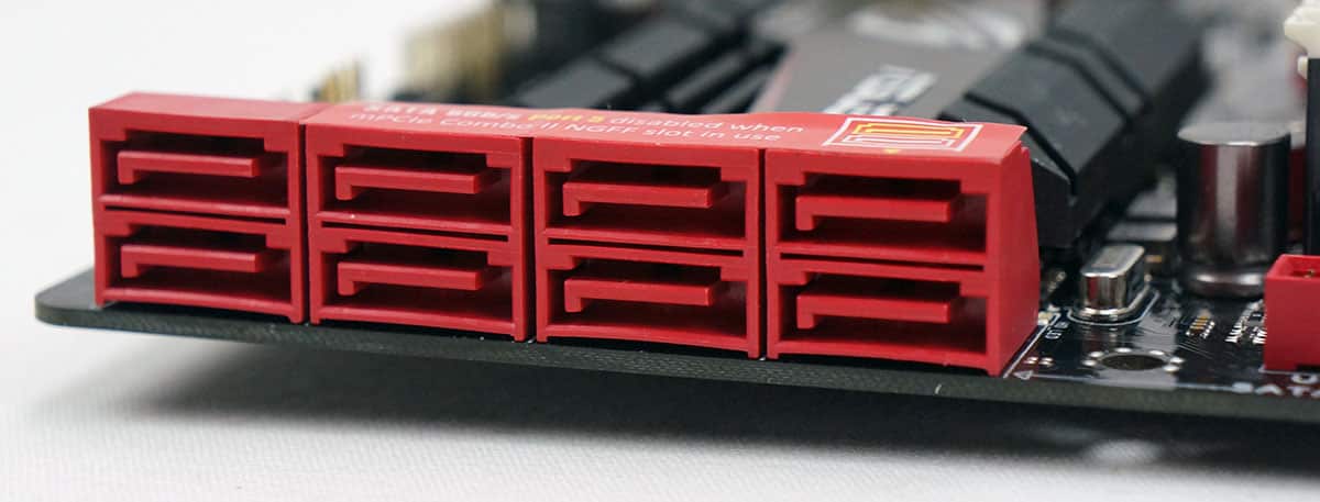
Towards the bottom end of the board there are 8 SATA 6GB/s connectors. The top six are controlled by the Z87 chipset and support RAID 0/1/5/10. The bottom two are controlled by the ASMedia ASM1061 controller. It is worth noting that SATA port 5 gets disabled if you are using NGFF storage on the mPCIe combo card. All SATA ports are angled away from the board to make them easier to connect and so they are not in the way of your graphics cards.
Along the bottom of the board you have the rest of your buttons and connections. From right to left you have your front panel headers, a 4pin fan connector, DirectKey button, TPM header, USB 2.0 header, ROG_EXT header, reset button, power button and HD audio header. The DirectKey button will instantly boot you into the BIOS, which is very useful. Also I always like seeing power and reset buttons on motherboards.
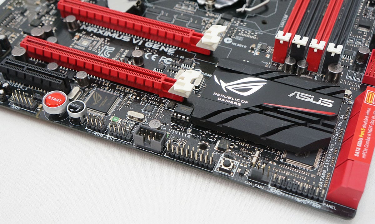
The SupremeFX sound chip is actually right on the motherboard itself. To cut down on interference ASUS has implemented “Red Line”, which literally cuts the PCB into two parts. You can see the cutout in the photo below. The chip itself also has an EMI protection cover. The SupremeFX features 8-channel HD audio that is equal in power, clarity and range to dedicated sound cards. For more information on the SupremeFX chip be sure to check out our features page.
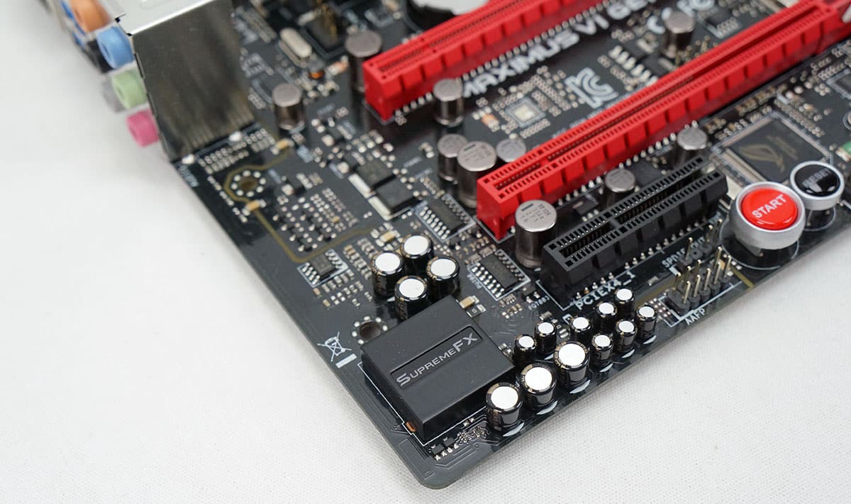
Being that this is a Micro-ATX motherboard your expansion slots are a little bit limited, but you do have two PCI-Express 3.0 x16 slots and a single PCI-Express 2.0 x4 slot. If you have one card installed it will run at x16 speeds and when you have two cards installed they will both run at x8 speeds. This board does support Quad-SLI and Quad-CrossFireX technology, so you could run two dual-GPU cards if you wanted to. Right above the top PCI-Express x16 slot is another 4pin fan connector, giving you a total of three not including the CPU and CPU optional fan connectors.

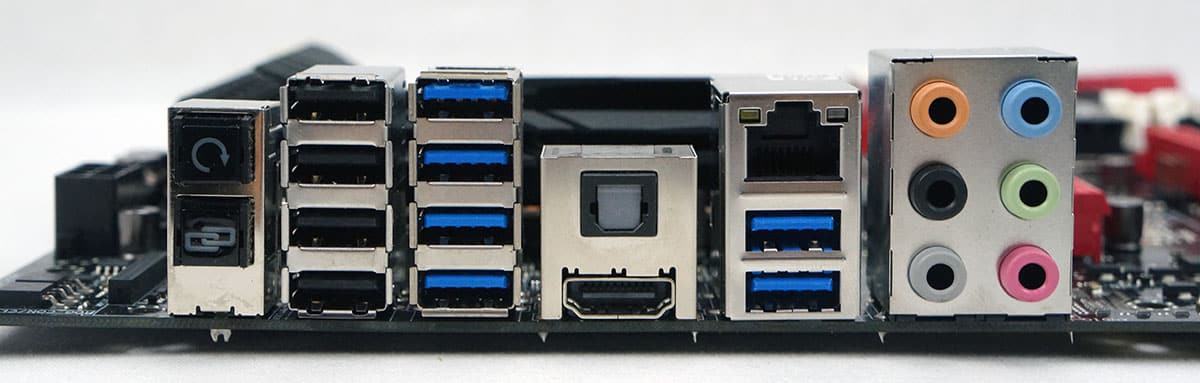
Finally we have the rear I/O. From left to right you have the BIOS flashback button, ROG connect button, 4 USB 2.0 ports, 4 USB 3.0 ports, optical audio out, HDMI out, Gigabit Ethernet, two more USB 3.0 ports and audio connections.


Would you prefer this board to the Gigabyte Sniper M5? I’ve bought two of the gigabyte boards in the last week. First DOA board I’ve ever had and I got two in a row so I think I’ll try this Asus board next instead.
Maybe I’m just old, but maybe not…is it not better to have 1 really good GPU, compared to having 2 (or more) mediocre GPU’s?
I know that ROG is a great standard of components; but does a typical gamer really need to run more than 1 GPU (if it’s of a high-end variety)…unless he/ she is running 4K graphics?
You are correct, if you are gaming in 1080p 1 GPU is all you are going to need. You will not see a huge difference in performance even if you add another GPU, this is only seen in 4K and multi-display gaming.