Installation
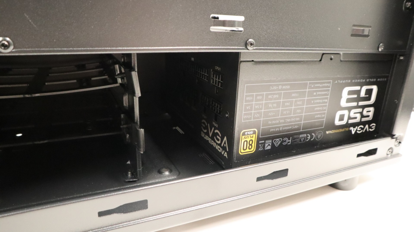
We always like to start our builds with the power supply first, and that is no different with this case. What is different however, is that you first have to attach the included power supply bracket to the power supply before you can go any further.
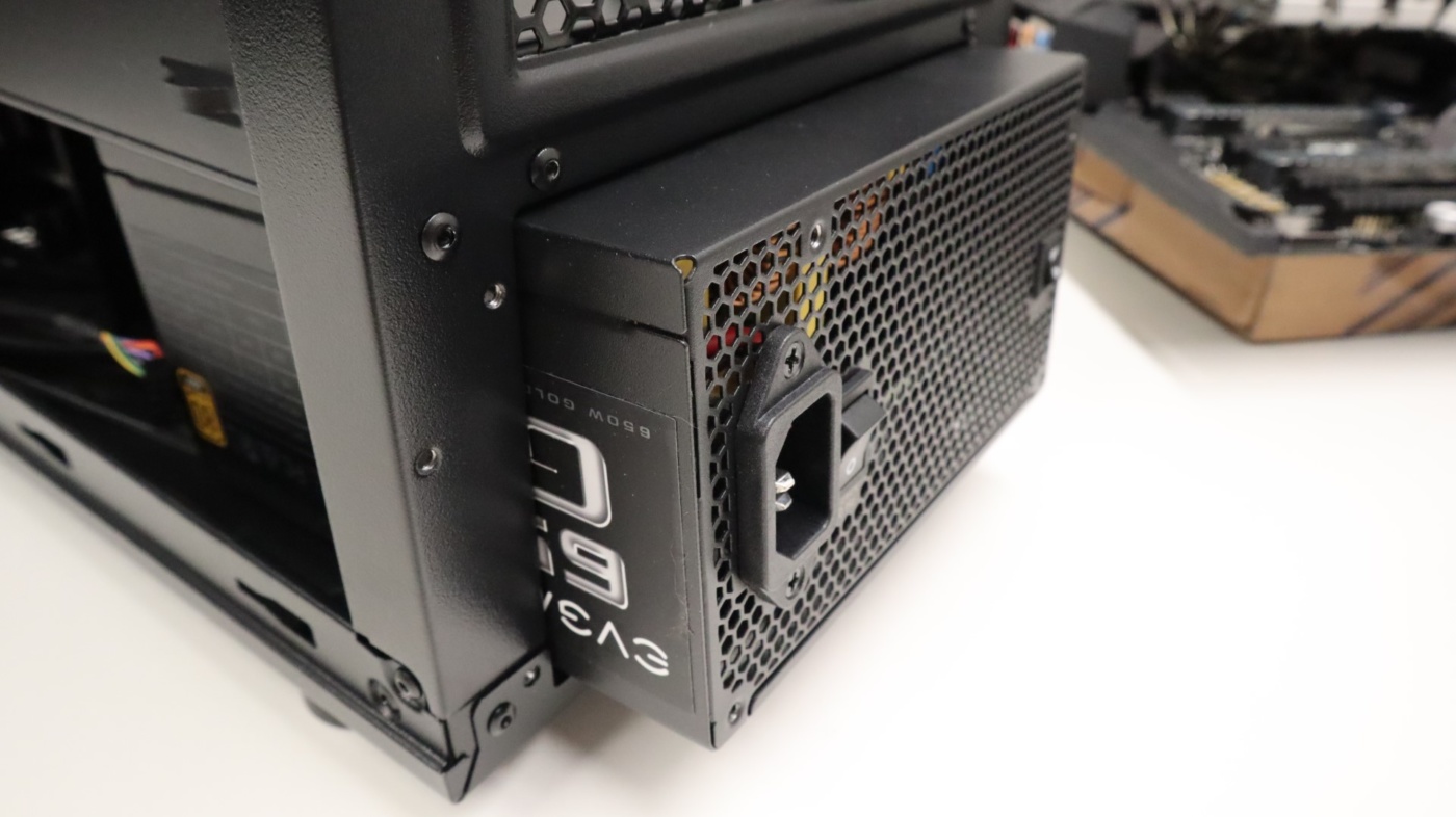
With the bracket attached, you can then attach the power supply to the case.
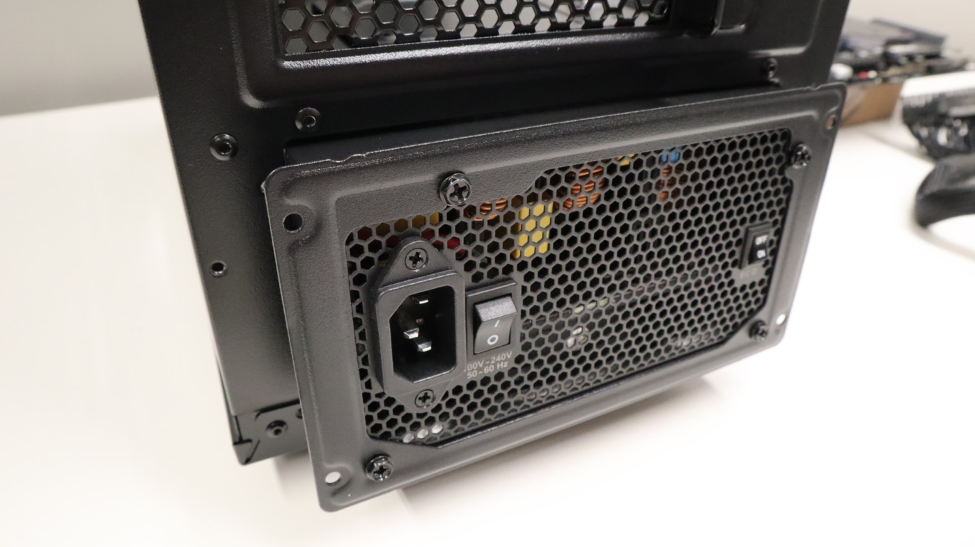
With our power supply installed, we were a bit worried about the room we would have to connect our modular cables, and since we weren’t going to be using any 3.5″ drives in our build, we decided to remove this drive cage. Unfortunately for us, this meant that we would also have to remove the power supply, as there is not enough of a gap between the case frame and the power supply shroud for the cage to come out. And while this case does support power supplies up to 170mm in length, it may require adjustment like in our case.
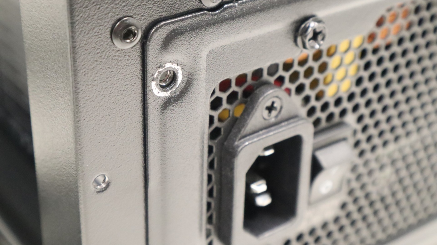
We do want to point out a bit of a quality issue we noticed when reinstalling our power supply. It appears that there isn’t much of a primer used for the case’s paint job, as at each screw location, the paint had easily flaked away when we removed our screws from the case. And while this bare metal will be covered up by screws, it indicates a possible cost-savings measure that was taken by FSP.
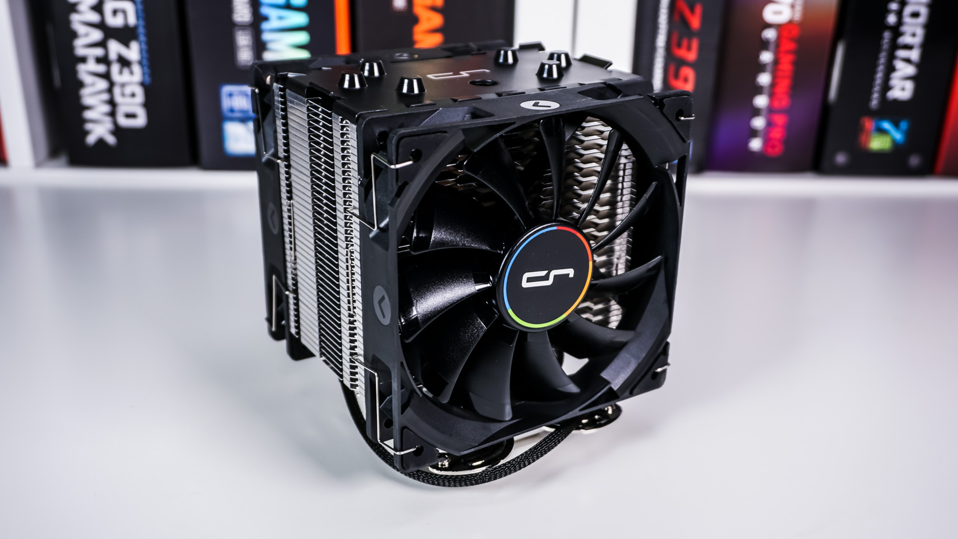
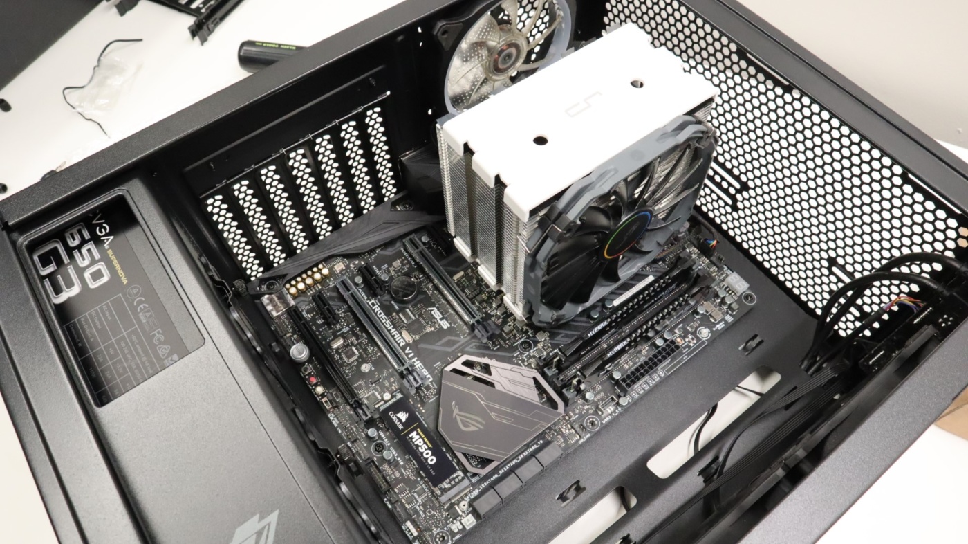
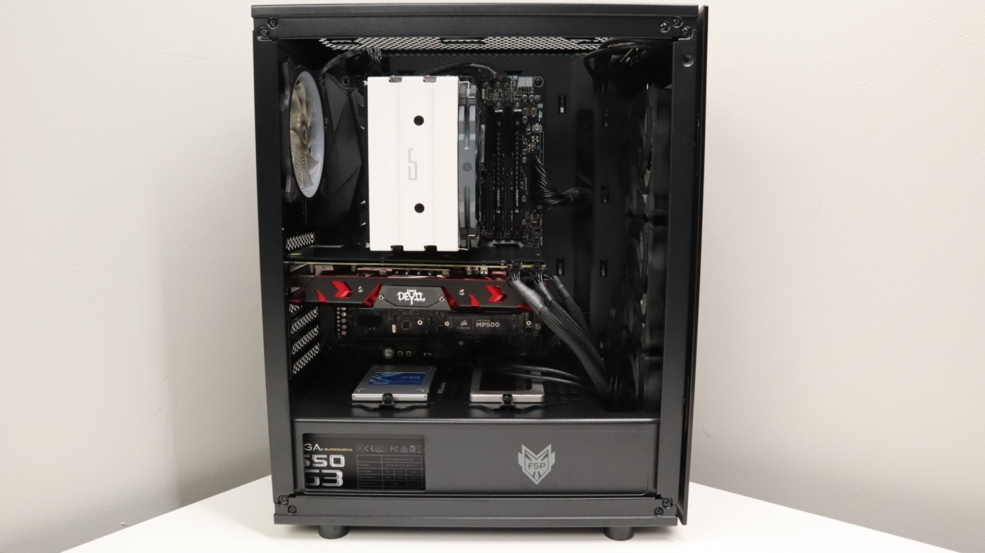
With plenty of room for our power supply, we were ready for our motherboard installation. We had no issues attaching the I/O shield to the case, and once it was in place, we simply guided the motherboard into its resting spot. Getting the board into the right spot was a bit tight in the CMT340, as there isn’t much extra room for your hands, especially near the bottom of the board. The CMT340 has room for CPU coolers up to 160mm in height, and our Cryorig H5 Universal fit just fine. With our motherboard in place, we were ready for our next component.
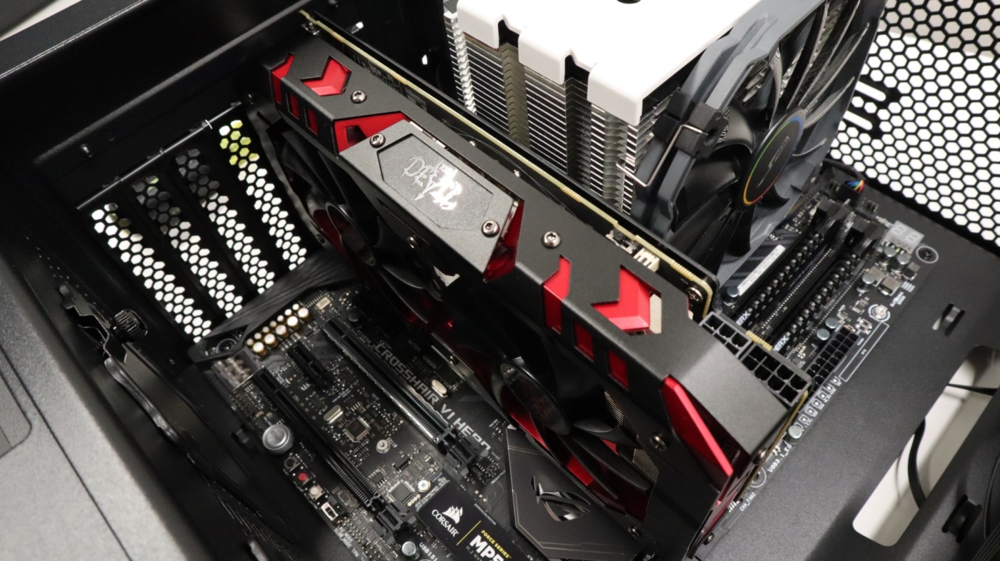
Our graphics card was up next, and went in without much effort. The CMT340 supports graphics cards up to 350mm in length, and the only issue we had was a bit of tightness getting the I/O portion of the card into the opening at the back of the case. With a bit of flexing, we were able to complete our installation and secure the card with the appropriate screws.
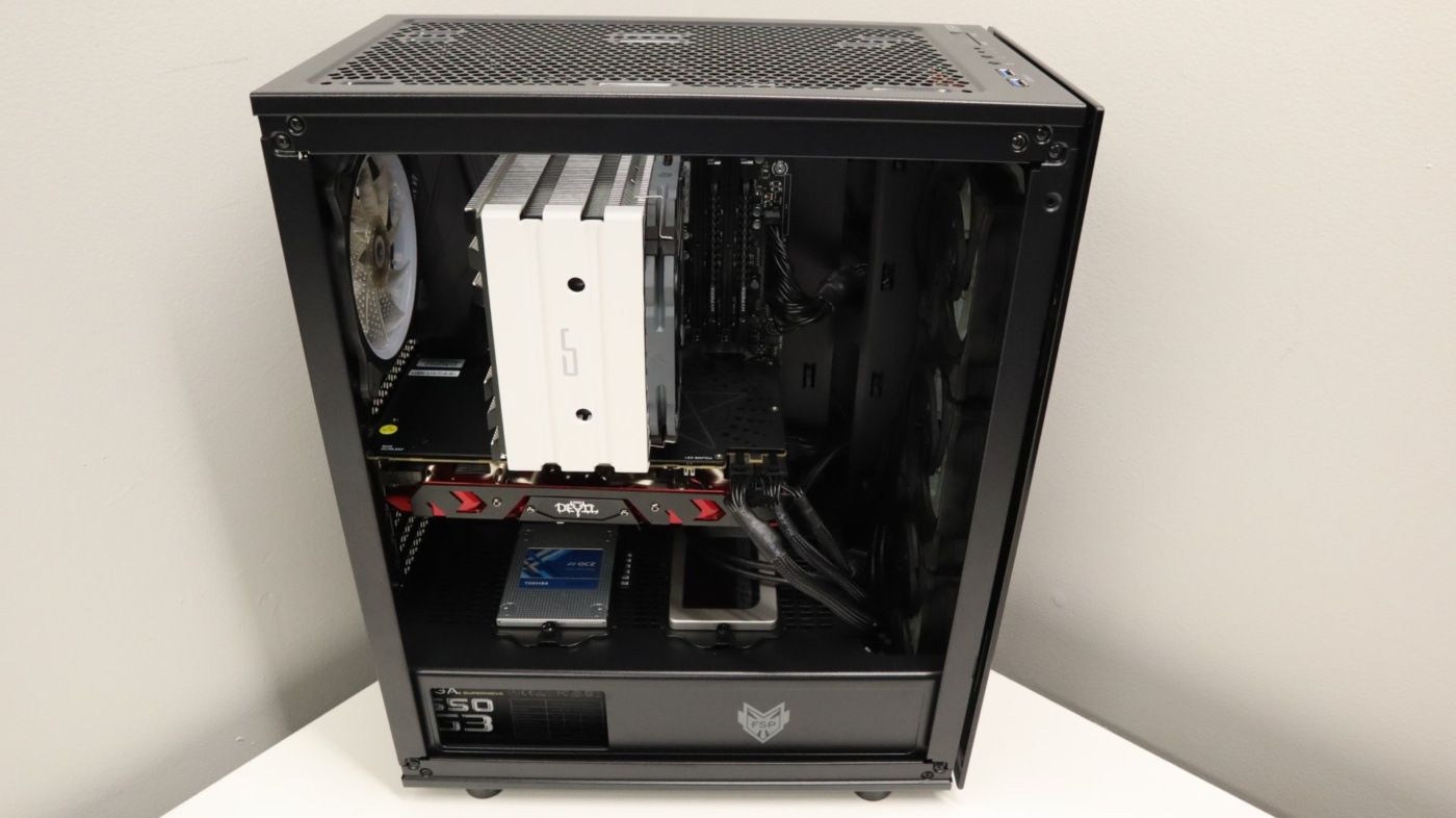
The final process in our build process is the cabling to connect all of our various components. Unfortunately, there aren’t a ton of cutouts on the interior of the case to route cables, so we had to use a few alternative routes. For example, we often use a cutout in the power supply shroud to route our video card power cables. In the CMT340, this isn’t really an option, unless you route them back towards the motherboard, which we have used for our 2.5″ drives. Instead, we ran these power cables towards the front of the case, and down below.
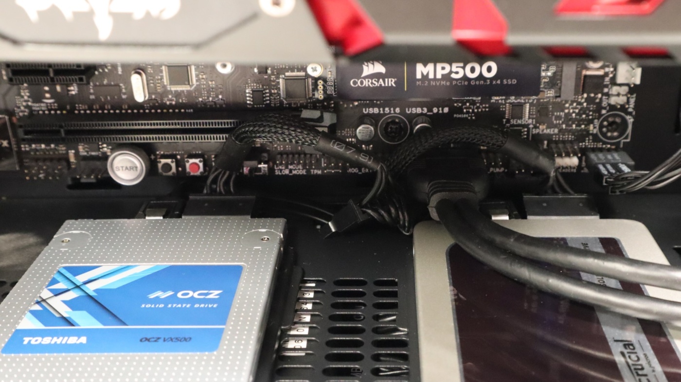
Additionally, mounting our 2.5″ drives to the top of the power supply shroud was a process that tested our patience. The drive trays sit deep enough in the case that it is quite difficult to connect the data and power cables to drives. And even after the drives are fully connected, the cables have to make pretty tight turns to route down through the top of the power supply shroud, especially the SATA power cabling.
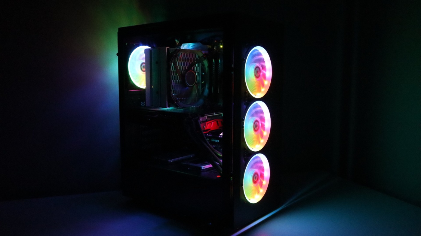
The “behind the scenes” cabling turned out to be pretty clean, with plenty of room for excess cables to reside underneath the power supply shroud. The included zip ties were helpful in keeping items in their place.
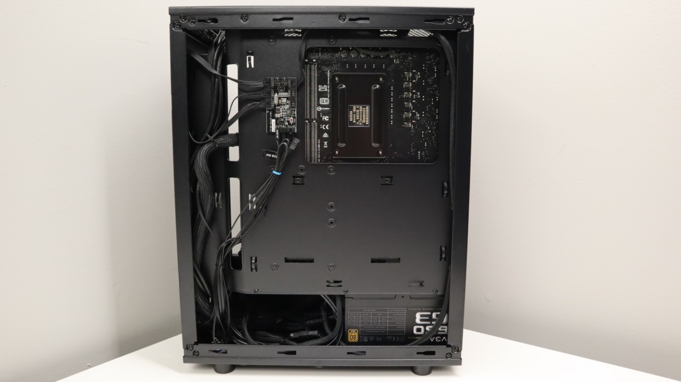
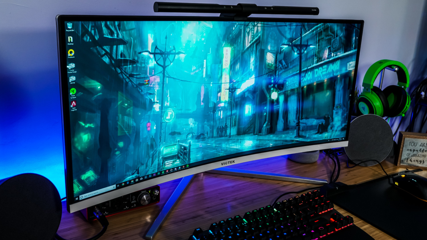
Overall, the build process in the FSP CMT340 was pretty straightforward, and our results look pretty good, considering the limited cable management options.